New thread for new approach. Full upgrade. (1 Viewer)

OP
OP
PeteMallorca
Jun 26, 2022
176
64
Mallorca, Spain
Funster No
89,512
MH
Benimar sport 340
Exp
Benimar sport 340
Yes it means 2x 95mm2 for positive and 2 for negative.
If your 3 batteries are in paralel, then between them should be 70mm2, or each battery to a buss bar.
And before you say they are overkill, it’s a 2,18% or 0,3v voltage drop at 4m with the 2x95mm2. Victron table is spot on.
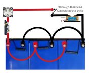
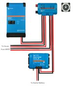
Thanks Raul. So it's OK for the cables between the batteries to be 70mm2? I have 2 beside each other and the third is about 3 feet away. Then I plan to run through a double poll isolation and then to a busbar.

Does that sound OK?
 
Dec 2, 2019
3,602
7,784
Amersham
Funster No
67,145
MH
van conversion
Exp
Since 2019
As long as you pick up from batt.1 and batt3 with 2x95mm to the isolator and then bussbar.
 
OP
OP
PeteMallorca
Jun 26, 2022
176
64
Mallorca, Spain
Funster No
89,512
MH
Benimar sport 340
Exp
Benimar sport 340
As long as you pick up from batt.1 and batt3 with 2x95mm to the isolator and then bussbar.
Got it. So 70mm2 between each battery and then 2x95mm from first battery negative and 2x95mm from third battery positive?

Subscribers  do not see these advertisements

 
OP
OP
PeteMallorca
Jun 26, 2022
176
64
Mallorca, Spain
Funster No
89,512
MH
Benimar sport 340
Exp
Benimar sport 340
Fuses!
Please correct me if any of this is wrong!

I'm just going through each specifications sheet, for the correct size fuse for each item.

For the "blue smart ip22 charger 12v - 30A"
I couldn't find a fuse rating but I did find a possible situation (Please read this https://community.victronenergy.com...-smart-ip22-charger-trips-automatic-fuse.html).

Can anyone suggest what "Soft Start" I will need for this and what fuse rating that I should add?

I plan to fit an AC socket for the "blue smart ip22 charger 12v - 30A", so that it can be taken out of the camper, to charge the batteries separately, at any time.

So I'm thinking of, AC in, through the main AC trip, through a ??A fuse, to a "Soft Start" and then to the socket. The fuse and soft start will be next to the socket and a notice stating that the socket is suitable for ?? Amps and it has a Soft Start limiting the initial inrush current to ???A.

If im completely wrong, please dont laugh too loud. If you can suggest a better way, please tell me your ideas.
 
Apr 27, 2016
6,876
8,004
Manchester
Funster No
42,762
MH
A class Hymer
Exp
Since the 80s
If you are going to implement that suggested solution, with a time-delay relay and a wirewound power resistor, you could put them in the charger mains lead, using a small box with a cable gland going in and out. That way, the solution stays with the problem as you move the charger location.
 
Mar 30, 2019
2,777
5,148
Cardiff, UK
Funster No
59,476
MH
Coachbuilt
Exp
Since 2016
I have an IP22 12vx30amp charger. Mine works perfectly well just plugged into one of my vans existing 230v sockets (I have one conveniently near the batteries). You might consider trying your new charger to see if it actually trips your supply before worrying about building a solution (for a problem you may not have).

Subscribers  do not see these advertisements

 
OP
OP
PeteMallorca
Jun 26, 2022
176
64
Mallorca, Spain
Funster No
89,512
MH
Benimar sport 340
Exp
Benimar sport 340
Hi Guys, it's getting close to getting everything installed.

I have a some questions on the batteries. I'm sorry for so much detail, making it a long post but I'm trying to prepare everything for a quick change over, when the time comes.

Question 1, Should I have anything between each battery? The original packing had a high density foam packing and I was thinking to put this between them. Ive added photos showing all batteries and a close up of the foam between 2 of them.

I have sent back the Pheonix 12v 3000VA inverter and replacing it with a Multiplus 12v 3000VA. Mainly for the ATS and the charging, on the rare occasion that I do have external AC power. Also giving me an emergency source to charge the batteries, if needed. Then I can remove the original ATC and associated birds nest of cables.

I will mount the Multiplus where the red arrow is pointing. It's very close to the batteries and the starter batteries are under the drivers seat, in front of this.

Question 2, If I mount the shunt and the main battery On/Off plus fuse, inside the battery area, with the battery On/Off operating from the outside, behind the drivers seat. What is the best way to run the cables? Should I have 2 busbars, inside the battery area and then run the cables to the Multiplus and to the system + and - ? Or, Should I use something like the Bulkhead fittings (Photo) and put the busbars on the outside, beside the Multiplus? Or, any other suggestions.

Question 3, Will I still need 2 x 95mm² cables to the Multiplus?

Question 4, Should I have another main fuse and On/Off before the cable going to the system + and - ?

Any suggestions welcome. Thanks.
 

Attachments

  • Screenshot_20221014-115148_Chrome.jpg
    Screenshot_20221014-115148_Chrome.jpg
    377.9 KB · Views: 41
  • Screenshot_20221014-115252_Chrome.jpg
    Screenshot_20221014-115252_Chrome.jpg
    317.9 KB · Views: 41
  • Screenshot_20221014-115311_Chrome.jpg
    Screenshot_20221014-115311_Chrome.jpg
    265.8 KB · Views: 44
  • 20221014_120456.jpg
    20221014_120456.jpg
    273.9 KB · Views: 45
  • 20221014_121457.jpg
    20221014_121457.jpg
    147.4 KB · Views: 46
Apr 27, 2016
6,876
8,004
Manchester
Funster No
42,762
MH
A class Hymer
Exp
Since the 80s
I think the foam packing would impede the flow of heat from the batteries on the inside, so I would leave it out. You'd like the batteries to be all at a similar temperature, and the foam packing won't help that.

Subscribers  do not see these advertisements

 
Apr 27, 2016
6,876
8,004
Manchester
Funster No
42,762
MH
A class Hymer
Exp
Since the 80s
Will I still need 2 x 95mm² cables to the Multiplus?
Using the Voltage Drop Calculator, for the worst case scenario of 250A (3000W) at 12V, then for a 4m run it requires more than 95mm2, probably 2 x 70mm2 or 2 x 95mm2. However for a 1m run 35mm2 cable gives a voltage drop of 2.33%, which is OK. If you go for 70mm2 then the voltage drop is only 1.21%.

You can try the numbers juggling yourself, with this Voltage Drop Calculator, but it only goes up to 95mm2.

I have my own spreadsheet that does calculations for any size of cable, but I think if 95mm2 cable is not good enough you should be seriously rethinking the layout. Your new approach is a big improvement.
 
Apr 27, 2016
6,876
8,004
Manchester
Funster No
42,762
MH
A class Hymer
Exp
Since the 80s
If I mount the shunt and the main battery On/Off plus fuse, inside the battery area, with the battery On/Off operating from the outside, behind the drivers seat. What is the best way to run the cables?
The best way to ensure equal voltage on all 3 batteries is to run equal length links from each battery to a common point. For the negatives, the shunt terminal is the obvious choice. For the positives, the first terminal on the isolator or fuse, whatever is nearest to the batteries.

This method is slightly better than the commonly used method of wiring the positive and negative load cables to battery 1 and battery 3.

Subscribers  do not see these advertisements

 
Dec 2, 2019
3,602
7,784
Amersham
Funster No
67,145
MH
van conversion
Exp
Since 2019
Q3- your multiplus comes with a operating/ installation manual. Look in the manual what cable is required. If it says 2x 95mm2, then that’s what you should use. Apart from voltage drop, you need to prevent DC ripple. To do that you need to stay within specified cable size in the manual.
Q4- one fuse it’s enough closer to the source to protect the hole conductor. A fuse with all its connections adds resistance. You want to keep this to minimum. One fuse at source it’s enough.
 
Apr 27, 2016
6,876
8,004
Manchester
Funster No
42,762
MH
A class Hymer
Exp
Since the 80s
Q3- your multiplus comes with a operating/ installation manual. Look in the manual what cable is required. If it says 2x 95mm2, then that’s what you should use. Apart from voltage drop, you need to prevent DC ripple. To do that you need to stay within specified cable size in the manual.
The manual for my Multiplus 3000 has cable sizes for the 12V, 24V and 48V versions (mine is the 48V). It says for 0 to 5m length, use 2 x 50mm2 cable.
 
Dec 2, 2019
3,602
7,784
Amersham
Funster No
67,145
MH
van conversion
Exp
Since 2019
The manual for my Multiplus 3000 has cable sizes for the 12V, 24V and 48V versions (mine is the 48V). It says for 0 to 5m length, use 2 x 50mm2 cable.
Yes, for 12v use 2x 50mm2, 24v 50mm2 and 48v 35mm2. All up to 5m length max.

4BAEA496-4D85-41BA-BC3E-0E19C3EC8ECC.png

Subscribers  do not see these advertisements

 
Aug 18, 2011
12,141
18,010
derbys
Funster No
17,808
MH
AUTOSLEEPER SYMBOL
Exp
since 2007.Tugger before since 1970
Are lithium batteries affected by high temperature ? Coming down through France in Sept and it was hot,,mid to high 30 s my leisure battery dropped to 12 volts and even whilst driving would not go back to its normal 13.4 to 14 volt..A couple of days later all back to normal..BUSBY.
 
Dec 2, 2019
3,602
7,784
Amersham
Funster No
67,145
MH
van conversion
Exp
Since 2019
Yes they are affected by high temperature. In your case, I think high temperature protection kicked in, until normal temperature restored.
 
Feb 3, 2020
205
254
hartlepool
Funster No
68,502
MH
Hi Top
Exp
Hit the road in 2014
all to confusing to me but wish you well

Subscribers  do not see these advertisements

 
OP
OP
PeteMallorca
Jun 26, 2022
176
64
Mallorca, Spain
Funster No
89,512
MH
Benimar sport 340
Exp
Benimar sport 340
I think the foam packing would impede the flow of heat from the batteries on the inside, so I would leave it out. You'd like the batteries to be all at a similar temperature, and the foam packing won't help that.
Thanks autoroute. That makes sense. I was only thinking about the batteries being tight together.

Thanks.
 
OP
OP
PeteMallorca
Jun 26, 2022
176
64
Mallorca, Spain
Funster No
89,512
MH
Benimar sport 340
Exp
Benimar sport 340
Using the Voltage Drop Calculator, for the worst case scenario of 250A (3000W) at 12V, then for a 4m run it requires more than 95mm2, probably 2 x 70mm2 or 2 x 95mm2. However for a 1m run 35mm2 cable gives a voltage drop of 2.33%, which is OK. If you go for 70mm2 then the voltage drop is only 1.21%.

You can try the numbers juggling yourself, with this Voltage Drop Calculator, but it only goes up to 95mm2.

I have my own spreadsheet that does calculations for any size of cable, but I think if 95mm2 cable is not good enough you should be seriously rethinking the layout. Your new approach is a big improvement.
Thanks autorouter, I did check the cable size on that Web site before writting the post. It did show considerably smaller cables for the Multiplus at the length that I'm hoping to keep them.

Since reading what Raul has said, about DC ripple, I'm not so sure now.

Thanks for the compliment. The planning stage is taking an eternity but it will all be worth it in the end.

Thanks
 
OP
OP
PeteMallorca
Jun 26, 2022
176
64
Mallorca, Spain
Funster No
89,512
MH
Benimar sport 340
Exp
Benimar sport 340
Using the Voltage Drop Calculator, for the worst case scenario of 250A (3000W) at 12V, then for a 4m run it requires more than 95mm2, probably 2 x 70mm2 or 2 x 95mm2. However for a 1m run 35mm2 cable gives a voltage drop of 2.33%, which is OK. If you go for 70mm2 then the voltage drop is only 1.21%.

You can try the numbers juggling yourself, with this Voltage Drop Calculator, but it only goes up to 95mm2.

I have my own spreadsheet that does calculations for any size of cable, but I think if 95mm2 cable is not good enough you should be seriously rethinking the layout. Your new approach is a big improvement.
Thanks autorouter, I did check the cable size on that Web site before writting the post. It did show considerably smaller cables for the Multiplus at the length that I'm hoping to keep them.
Q3- your multiplus comes with a operating/ installation manual. Look in the manual what cable is required. If it says 2x 95mm2, then that’s what you should use. Apart from voltage drop, you need to prevent DC ripple. To do that you need to stay within specified cable size in the manual.
Q4- one fuse it’s enough closer to the source to protect the hole conductor. A fuse with all its connections adds resistance. You want to keep this to minimum. One fuse at source it’s enough.
Thanks Raul, I've downloaded the Multiplus Manual and it does say 2 x 50mm².

I've got a Linx distributor that I was going to put on the other side of the van but I'm now thinking that this would be better next to the Multiplus, with the Orion 12 - 12 - 30A above it (for better cooling).

What do you think about 1 x 95mm², from the Lynx to the Multiplus? Giving me the extra output / Input for the Lynx.

Also, what did you think of the "Through bulkhead" connectors? If I could come through the Bulkhead, at the end of the Lynx and connect directly to it, that would make the cable length shorter because it won't need to be curved so much.

Thanks.
 
Dec 2, 2019
3,602
7,784
Amersham
Funster No
67,145
MH
van conversion
Exp
Since 2019
The lynx near the multiplus it’s very helpful. The bar on the lynx it’s rated at1000a. And one 95mm2 will be plenty as it will be close to the linx. Going trough the bulkhead is not a problem as long as you have a very good grommet at the metal contact point, then fixed well to eliminate movement. Some insulated cleats that grubs the cable tight.
 
Apr 27, 2016
6,876
8,004
Manchester
Funster No
42,762
MH
A class Hymer
Exp
Since the 80s
Also, what did you think of the "Through bulkhead" connectors?
They are very good if you want to prevent fumes, water or even fire from going through a bulkhead (or firewall as our US friends call them). Nothing wrong with using them in a cupboard wall, but a padded hole is also quite OK.
 
OP
OP
PeteMallorca
Jun 26, 2022
176
64
Mallorca, Spain
Funster No
89,512
MH
Benimar sport 340
Exp
Benimar sport 340
The lynx near the multiplus it’s very helpful. The bar on the lynx it’s rated at1000a. And one 95mm2 will be plenty as it will be close to the linx. Going trough the bulkhead is not a problem as long as you have a very good grommet at the metal contact point, then fixed well to eliminate movement. Some insulated cleats that grubs the cable tight.
Thanks a lot Raul, as soon as the Multiplus arrives, I can mount it and start working out the cable lengths. Thanks for your help.

Subscribers  do not see these advertisements

 
OP
OP
PeteMallorca
Jun 26, 2022
176
64
Mallorca, Spain
Funster No
89,512
MH
Benimar sport 340
Exp
Benimar sport 340
They are very good if you want to prevent fumes, water or even fire from going through a bulkhead (or firewall as our US friends call them). Nothing wrong with using them in a cupboard wall, but a padded hole is also quite OK.
Thanks a lot autorouter, I'm happier with the solid bar running through the wall, it's thin panels on each side, onto a frame. Then there's no excessive bending of the heavy cables and the length will be considerably shorter. I'm now looking forward to ordering the cables 😁 as. Thanks for your help.
 
OP
OP
PeteMallorca
Jun 26, 2022
176
64
Mallorca, Spain
Funster No
89,512
MH
Benimar sport 340
Exp
Benimar sport 340
Update.

I've been busy trying to get parts shipped over here and planning the system and layouts. I think that this is the last stage and I'm looking for opinions and any advice that anyone can give me. I'm sorry for the long thread but I'm sure that you guys who know what you're doing, will appreciate the detail.

Here goes.....


I plan to have 3 sections, because of available space.

The first section is the Battery section (image 1)

The batteries are fitted, in place. I have yet to decide on the exact position of the Lynx distributor, that will be the other side of the 25mm bulkhead, that is next to the Battery terminals.

I have ordered:
1 x Blue Sea 5502 Fuse Block Class T 225-400 Amp.

2 x Blue Sea Systems Class T Fuses

1 x Blue Sea Systems 3000 HD-Series Heavy Duty On-Off Battery Switch. 600A 32vdc.

I have the Victron 1000A Smart Shunt. And a Victron Smart Battery Sense in use now.

For this section, I would like to confirm that its correct to use:

70mm² cable to connect the batteries together and 95mm² to connect from the negative of the last battery to the smart shunt and then to the Lynx.

95mm² to connect from the first battery + to the T fuse, then the main switch, then the Lynx positive.

Also because these 95mm²cables will be very short, I have been thinking about using some copper bar, from the smart shunt to the through bulkhead negative connector. And, from the T Fuse to the switch and from the switch to the through bulkhead positive connector. The Smart Shunt, T Fuse holder and the Battery Switch will be physically mounted to the bulkhead and then flexible 95mm² cable to the batteries.

If you agree with this option, what size bar would you suggest?

Also, what size round bar should I use, for the through bulkhead fittings? I plan to get these made from copper round bar, drilled and threaded, with mate stud screwed completely through it and protruding both ends, one for the battery cables / copper bar and the other directly into the Lynx connections lugs.

---------------------------------------------------------

The second section is the Inverter section ( image 2).

I have the Victron MultiPlus-II 12_3000_120-32 230V and the Victron Lynx distributor fitted. I might have to move the Lynx slightly, to allow for ventilation fans, for the MultiPlus-II and the victron Orion-Tr Smart DC-DC Charger Isolated 12 12 30.

I have added Fuse values, that I think would be correct but this will depend on the cable size that I end up using. I have planned for:

1, 400A Fuse for the MultiPlus-II. The cables will be about 0.5m and the plan is to use single 95mm² cables.

2, 150A fuse (not 250A as it says on the image.) for the 12v House system. This will include the original 12v distribution box (CBE DS300) and the new 8 way (100A max) Fuse panel.

The original distribution board, electrical diagram, shows a 50A fuse from the house batteries. The new fused 12dc distribution panel is rated at 100A.

The house section will be about 3m away from the Lynx. The plan is to use 50mm² cable for this.

3, 70A fuse, to and from the Victron SmartSolar MPPT 150 l 60 Tr.
This is in the house section and again will be about 3m away from the Lynx. The plan is to use 25mm² cable for this.

4, 60A fuse, from the Orion-Tr Smart.
This will be about 0.5m away from the Lynx and about 1m away from the Starter batteries. There will be a 60A fuse at the Starter battery.
The plan is to use 6mm² for both of these.

I am also thinking to run an addition outlet from the "Add on" end of the Lynx, with a Blue sea MRBF Terminal Fuse Block - 30 to 300A, with a 30A Blue Sea MRBF Terminal Fuse, for positive and a short copper bar for negative. To run about 0.25m to an Anderson 50A socket. To be used as a direct battery connection, for my Victron Blue Smart 12 - 30 Charger (portable, with AC mains plug). To help top up the battery bank, if needed. This way, i can have a second Anderson socket with cables and lugs, to bolt direct to each battery, if I need to fully charge them seperately.

Any ideas on this?
---------------------------------------------------------

The third section will be the House section (image 3).

Here will be:

1, 3 x Blue Sea Systems 300 Amp 48v m-Series Battery Switches. (ORDERED)

2, The new 12v, 12 way, fused distribution board. (GOT IT)

3, The Victron Cerbo GX. (GOT IT)

The Victron SmartSolar MPPT 150 l 60 Tr. (GOT IT)

4, A Solar disconnected or dc circuit breaker. (NEEDED)

I want to have the 3 Switches here because I can isolate each circuit, as and when I want or need to.

The cable from the lynx (To house 12v) to the the first switch will enter the switch and then continue to the second switch. The output of the first switch will supply the original dc distribution box. I am thinking to use 35mm² because the original distribution box will be about 7m away and the electrical diagram for it shows a 50A fuse from the house battery.

The output from the second switch will supply the new dc fuse distribution box. I am thinking to use 35mm² again because its rating is 100A but its only about 0.25. Away from the switch.

The cable into the third switch is coming from the lynx (From MTTP), and the output will supply the mttp. I am thinking that the cable will continue as 25mm² cable.

I have been considering not installing this switch and putting a low Amperage switch on the MTTP remote on/off connector but I'm reluctant to use that because it might be needed for any system settings that use Victron relays to switch it off, for example, during some kind of alarm. What are your thoughts on this?

The Solar disconnected or dc circuit breaker, I'm not sure which is the best option, any suggestions welcome.

I guess that I will have to wait until I buy the new panels, to know what amperage or voltage that the Solar dc circuit breaker will need to be. Maybe not such a problem if using a solar disconnect?
---------------------------------------------------------

I will be running a new cable from the Shore Power inlet, to the MultiPlus-II, AC IN. This will be used on rare occasions but will double as an inlet from my Champion 2200 Watt Inverter Generator-The Mighty Atom - Dual Fuel.

For the 2 AC out, from the MultiPlus-II, I was thinking about a small consumer unit, in the Inverter section, to house 2 x RCD's and 2 x Main MCB's, one of each, for each AC out. Then go to a second consumer unit, in the House section, where each AC circuit will have its own MCB's for each circuit.
I am planning this way because there is very little room in the Inverter section but I wanted to protect the cables going across the van, to supply the House AC circuits.

---------------------------------------------------------

Have I covered everything? I'm sorry for all the details but it saves a lot of questions, I hope :rolleyes:. Any suggestions on cables, Fuses or items that would be better, please let me have your opinions.

Thanks for any help.
 

Attachments

  • IMG_20221116_140707.jpg
    IMG_20221116_140707.jpg
    168.8 KB · Views: 25
  • IMG_20221116_140754.jpg
    IMG_20221116_140754.jpg
    192.2 KB · Views: 25
  • IMG_20221116_140849.jpg
    IMG_20221116_140849.jpg
    240.8 KB · Views: 25
OP
OP
PeteMallorca
Jun 26, 2022
176
64
Mallorca, Spain
Funster No
89,512
MH
Benimar sport 340
Exp
Benimar sport 340
It's getting closer to the full installation.!!!!!

What is your opinions on the panels in the attached PDF? They are the model No: JAM72S20-445/MR.

I'm planning for 2 of these, added to what will be finally installed.
Update:
2 x these panels.
1 x Victron SmartSolar 150/60.
1 x Victron Multiplus II, 12 - 3000.
3 x 200AH Lifepo4 batteries.
1 x Victron Orion DC 2 DC.
1 x Victron Cerbo GX.
1 x Victron SmartShunt 1000A.
1 x Victron Smart battery sense.
1 x Victron Lynx distributor.
1 x Victron Bluesmart 12 I 30 charger.
1 x Class T 400A
1 x Blue Sea HD3000 battery switch.
Plus other Fuses, switches etc.

Subscribers  do not see these advertisements


Attachments

  • 2570896.pdf
    944.1 KB · Views: 36

Join us or log in to post a reply.

To join in you must be a member of MotorhomeFun

Join MotorhomeFun

Join us, it quick and easy!

Log in

Already a member? Log in here.

Latest journal entries

Funsters who are viewing this thread

Back
Top