Hymer Step Switch .. How much !!! gulp

scotjimland

LIFE MEMBER
Joined
Jul 25, 2007
Posts
2,656
Likes collected
11,809
Funster No
15
MH
None
Just for information..

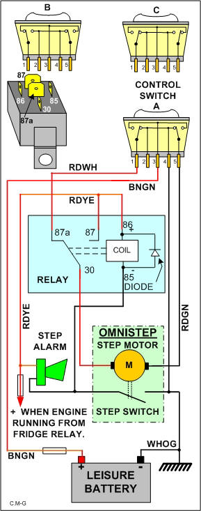
The toggle up/down door step switch on my Hymer is faulty .. it works up but not always down... it works intermittently .. proved with a multimeter..

checked the price and it's £74.33 .. :eek:

so contacted Becks (the dealer ) and they are supplying under warranty..


It's a Combined Step and Light Switch
https://caravan-parts.store.buegle....c-step-and-light-toggle-switch-/?k=:::5811278

https://caravan-parts.store.buegle....c-step-and-light-toggle-switch-/?k=:::5811278
Sounding more like a Yorkshireman every day Jim only it should be arrr much:D
terry
 
I will have to delete any bad posts about your van as I think I have sold Jill the idea of the 644, haha. Hope you get it sorted ok
 
Just for info. Omnistore Electric Step.

wiring drawing .. and fault finding


img3.jpg


The control switch is a DOUBLE CHANGE OVER SWITCH. (Not a double pole change over as this is subtly different) This switch contains two change over switches, one switch changes over when the rocker is operated in one direction and the other switch changes over when the rocker is operated in the other direction. So it carries out a few more functions than just a simple ON/OFF switch.

The Omnistep has a permanent magnet motor. This means that if you reverse the polarity the motor will run in the opposite direction. The switch is designed to do this. The motor rotates in one direction to extend and the other direction to retract.

Nominally 5 amps is the expected working current for the motor. If however you keep your finger on the switch after the step has fully extended or retracted then the motor will stall. Under this condition the current will increase to a significantly higher figure. Sometimes referred to as the “blocking current”.

The Omnistep has two electrical components, the motor which moves the step and a switch that is OPEN only when the step is fully retracted. At all other times the switch will be closed.

Firstly the system is designed to retract the step and sound the alarm should you start your engine with the step extended.

Under this condition the control switch is as shown in switch picture A. Battery negative is connected to terminal 4 of the switch and comes back out of the switch at terminal 5. It is connected to the right hand end of the motor with a RDGN wire.

When the engine is running the FRIDGE relay is energised from the vehicle alternator D+ terminal. The fridge relay applies 12 volts to both the fridge and also the step relay terminal 86 (coil+) and one side of the alarm.

If the step is extended then the step switch will be closed. This will provide a negative supply to the alarm causing it to sound, and also the other end of the relay coil (85) causing it to energise.. Now that the relay is energised the fridge supply which is also connected to the relay terminal 87 is routed by the closed contacts to relay terminal 30 and provides a positive supply to the Omnistep motor. The motor will rotate causing the step to retract. When fully retracted the step switch will open, the relay will release, the alarm will go silent.

With the engine turned OFF the rocker switch can be depressed causing the step to extend.

Under this condition the control switch is as shown in switch picture C. Battery negative is connected to terminal 4 of the switch and comes back out of the switch at terminal 1. It is connected to the relay terminal 87a (normally closed contact) and comes out of the relay at terminal 30. From here it is routed to the left hand end of the motor.

A positive supply from the leisure battery enters the switch at terminal 3 via a BNGN wire. This positive supply leaves the switch at terminal 5 which is routed via a RDGN wire to the right hand end of the motor causing the step to extend. When the step has extended you must leave go of the switch or the current will increase to 14 amps!

With the engine turned OFF the rocker switch can be depressed causing the step to retract.

Under this condition the control switch is as shown in switch picture B. Battery negative is connected to terminal 4 of the switch and comes back out of the switch at terminal 5. It is routed to the right hand end of the motor.

A positive supply from the leisure battery enters the switch at terminal 3 via a BNGN wire. This positive supply leaves the switch at terminal 1. It is connected to the relay terminal 87a (normally closed contact) and comes out of the relay at terminal 30. From here it is routed to the left hand end of the motor causing the step to retract. When the step has retracted you must leave go of the switch or the current will increase to about 14 amps!

Subscribers  do not see these advertisements

 
Try CAK Tanks. Looks like a CBE MCGD5/G which is listed at £9.77 on their webshop at http://www.leisurelines.net/cbe-59-c.asp . Probably plus vat and post though!
Steve

Hi Steve .. thanks..

it 'looks' like the same unit but it's not.. it is simply a two position rocker switch..
The Hymer switch has a PCB on the back with two relays.. see above drawing

dealer is supply me one FOC
 
Good for Becks! We found them to be fantastic when we bought our van from them and had a problem 2 weeks before the end of the year's warranty! Needed a new wiring loom at a cost of £650 - just glad we didn't have to pay for it.

Would have bought another van from them if they'd had what we wanted when we changed but unfortunately they didn't.

Denise
 
Hi @ScotJimland I have a slide out step that is wired in the fashion described in your post above.. ie a permanent magnet motor that is rs versed by a rocker type switch....
Can you tell me if all steps work on the same principle or can it be achieved in a different manner... before I read your post was going to try and look into this ,now I'm hoping you might save me the googling. .
Ta Andy.
 
Can you tell me if all steps work on the same principle or can it be achieved in a different manner..

Can't say for sure Andy .. but I imagine they would do..

Subscribers  do not see these advertisements

 
Can't say for sure Andy .. but I imagine they would do..
Thanks Jim, I'll have a look into it sometime..
A request from someone to look at their step and seem to remember reading somewhere about steps with timer function or cut outs which seemed to indicate a motor running one way but with cut outs at the appropriate point and then switched again to retract.
Thanks ...andy

that may be the case on some steps.. the ones on my RV were different.. the operated with the door opening and closing and also had a switch to park them either down or up

The Hymer system there is no limit switches, the step operates while the switch is held up or down, .. if you keep pressing the button when it reaches the extent of travel, the current go's up to 14 A ..
 
Last edited:
My switch works fine but my buzzer started getting a bit intermittent and has now stopped altogether.
Not sure I'll have time to check it before we head off to Italy just have to double check each time.
If anything goes wrong it'll be Jans fault as the step is her responsibility.
Haha dont reckon I'll get away with that.:):)
 
Just for info. Omnistore Electric Step.

wiring drawing .. and fault finding


img3.jpg


The control switch is a DOUBLE CHANGE OVER SWITCH. (Not a double pole change over as this is subtly different) This switch contains two change over switches, one switch changes over when the rocker is operated in one direction and the other switch changes over when the rocker is operated in the other direction. So it carries out a few more functions than just a simple ON/OFF switch.

The Omnistep has a permanent magnet motor. This means that if you reverse the polarity the motor will run in the opposite direction. The switch is designed to do this. The motor rotates in one direction to extend and the other direction to retract.

Nominally 5 amps is the expected working current for the motor. If however you keep your finger on the switch after the step has fully extended or retracted then the motor will stall. Under this condition the current will increase to a significantly higher figure. Sometimes referred to as the “blocking current”.

The Omnistep has two electrical components, the motor which moves the step and a switch that is OPEN only when the step is fully retracted. At all other times the switch will be closed.

Firstly the system is designed to retract the step and sound the alarm should you start your engine with the step extended.

Under this condition the control switch is as shown in switch picture A. Battery negative is connected to terminal 4 of the switch and comes back out of the switch at terminal 5. It is connected to the right hand end of the motor with a RDGN wire.

When the engine is running the FRIDGE relay is energised from the vehicle alternator D+ terminal. The fridge relay applies 12 volts to both the fridge and also the step relay terminal 86 (coil+) and one side of the alarm.

If the step is extended then the step switch will be closed. This will provide a negative supply to the alarm causing it to sound, and also the other end of the relay coil (85) causing it to energise.. Now that the relay is energised the fridge supply which is also connected to the relay terminal 87 is routed by the closed contacts to relay terminal 30 and provides a positive supply to the Omnistep motor. The motor will rotate causing the step to retract. When fully retracted the step switch will open, the relay will release, the alarm will go silent.

With the engine turned OFF the rocker switch can be depressed causing the step to extend.

Under this condition the control switch is as shown in switch picture C. Battery negative is connected to terminal 4 of the switch and comes back out of the switch at terminal 1. It is connected to the relay terminal 87a (normally closed contact) and comes out of the relay at terminal 30. From here it is routed to the left hand end of the motor.

A positive supply from the leisure battery enters the switch at terminal 3 via a BNGN wire. This positive supply leaves the switch at terminal 5 which is routed via a RDGN wire to the right hand end of the motor causing the step to extend. When the step has extended you must leave go of the switch or the current will increase to 14 amps!

With the engine turned OFF the rocker switch can be depressed causing the step to retract.

Under this condition the control switch is as shown in switch picture B. Battery negative is connected to terminal 4 of the switch and comes back out of the switch at terminal 5. It is routed to the right hand end of the motor.

A positive supply from the leisure battery enters the switch at terminal 3 via a BNGN wire. This positive supply leaves the switch at terminal 1. It is connected to the relay terminal 87a (normally closed contact) and comes out of the relay at terminal 30. From here it is routed to the left hand end of the motor causing the step to retract. When the step has retracted you must leave go of the switch or the current will increase to about 14 amps!
A lot of effort in that post Jim! Could do with that in resources section
 
My switch works fine but my buzzer started getting a bit intermittent and has now stopped altogether.

I would think that is the step switch that is dirty/sticky or corroded connections.

.. clean a spray with WD40 should sort it..

Subscribers  do not see these advertisements

 
Sometimes the buzzer 'drops off' its mounting point and then becomes inaudible. Perhaps Forestboy's is 'hanging by a thread'? Search for an earlier post regarding this issue if you want to research it a bit more - I have written about it before but cannot stop now to find the post.
 
This was the recent post I made but it refers to a Sprinter-based Hymer. On Fiat-based ones, I'm not sure where the buzzer is located but suspect it is near the Elektroblock.
Step issues.
 
On my Hymer a new switch for the habitation step has been installed (next to AC switch). But the normal switch has been disabled but is still there. Not sure why this has been done but can the original switch be restored?
 
Lots of arcing on that switch, I'd fit a suppressor across the motor to protect the relay and switch.

Subscribers  do not see these advertisements

 
On my Hymer a new switch for the habitation step has been installed (next to AC switch). But the normal switch has been disabled but is still there. Not sure why this has been done but can the original switch be restored?

Previous owner has probably fitted to save money buying the OEM unit

would need to see exactly what was done to the wiring to say if it were straight forward or not, but see no reason it cannot be restored to original ..
 
The previous owner spent a lot on the van which leads me to think the move of switches is more a location move as the new switch is on the dash. This would not cause a problem as arrive at site hit the switch and leave out till depart. But the dog does not like the steps and the only way to get her in is to jump when stairs are away!!
 
Ok.. then if you want it back as it left the factory shouldn't be too difficult.. are you happy messing with 12v wiring .. ?

If not I'd just leave as it is.. don't break it if it isn't broken
 
On my Hymer a new switch for the habitation step has been installed (next to AC switch). But the normal switch has been disabled but is still there. Not sure why this has been done but can the original switch be restored?

Probably cos like me :confused: they kept on getting into the drivers seat, belting up then finding the Fiddlesticksing step down :doh: I did think about wiring another switch up at the cockpit end but having read this thread I think its probably beyond my basic skills:RollEyes:

Subscribers  do not see these advertisements

 
Probably different but the internal electric blind on our euramobile some times had an intermitant fault it has 6 switches on it bough some electronic switches of eBay got electrictian at work to change 4 over now every think works cost pence

Joe
 
My switch works fine but my buzzer started getting a bit intermittent and has now stopped altogether.
Not sure I'll have time to check it before we head off to Italy just have to double check each time.
If anything goes wrong it'll be Jans fault as the step is her responsibility.
Haha dont reckon I'll get away with that.:):)

Same happen to me. Phoned Dave Newell and he said that it would be a faulty earth, quite common apparently. He fixed it at the same time as doing another job for me! No parts involved.

Dick
 
I thought Hymer B-class vans had a step-retracting switch on the dashboard as standard. Mine is a 2003 model and has one. It is to the right of the steering wheel (LHD) but will only retract the step, not extend it.
 
In case any Hymer owners have missed it, here is the entry from the 2004 model year manual. I note that the Fiat retracting switch is different to that fitted on a Merc chassis, and is on the other side of the steering wheel. Mine is a 2003 Merc-based B-class Star-Line with the rocker switch, so I presume it was a standard fitting around 2000-2005 at least.

upload_2015-7-5_15-24-57.png
 
In case any Hymer owners have missed it, here is the entry from the 2004 model year manual. I note that the Fiat retracting switch is different to that fitted on a Merc chassis, and is on the other side of the steering wheel. Mine is a 2003 Merc-based B-class Star-Line with the rocker switch, so I presume it was a standard fitting around 2000-2005 at least.

Just been out to check in case I had missed it .. but it's definitely not fitted on mine .. 2002 model .. also checked the manual and no mention of it ..

Good idea.. but as I mentioned earlier, I prefered the step control on my RV.. which operated with the door opening and closing and also had a switch to park them either down or up..

Subscribers  do not see these advertisements

 
Last edited:

Join us or log in to post a reply.

To join in you must be a member of MotorhomeFun

Join MotorhomeFun

Join us, it quick and easy!

Log in

Already a member? Log in here.

Latest journal entries

Back
Top