Homebrew solar tracker. (2 Viewers)

hilldweller

LIFE MEMBER
Dec 5, 2008
605
36,109
Macclesfield
Funster No
5,089
MH
Zilch Mk1
Exp
From Aug 2007
Why bother with GPS ?

Angle isn't that critical, you could just have 3 or 4 selectable for UK, France, Spain, Morocco. KISS.
 
OP
OP
Snowbird

Snowbird

LIFE MEMBER
Apr 24, 2009
11,818
22,346
Liverpool.
Funster No
6,422
MH
Fifth wheel.
Exp
Since 11-05-2000
The GPS also acts as a very accurate clock and calendar which doesn't need resetting if power is lost.

Could probably save ~£35 fitting a quartz clock, backup battery and using the Arduino to keep track of the date, resetting it any time you disconnect the leisure batteries - which would require a computer. As you point out, you'd then have to select which country you are in.

With GPS, in principle, this can be programmed once and forgotten about.
 

pappajohn

LIFE MEMBER
Aug 26, 2007
43,330
49,446
Dark side of the moon
Funster No
172
Exp
Since 2005
Dave, forget all this rubbish and fit 4 panels along yer roof.

angled individually for the time of day you will get sun on the panels (at least one of 'em) all day long.

just remember to park in an East/West direction and on a slope.

KISS ! :roflmto:
 
OP
OP
Snowbird

Snowbird

LIFE MEMBER
Apr 24, 2009
11,818
22,346
Liverpool.
Funster No
6,422
MH
Fifth wheel.
Exp
Since 11-05-2000
Dave, forget all this rubbish and fit 4 panels along yer roof.

angled individually for the time of day you will get sun on the panels (at least one of 'em) all day long.

just remember to park in an East/West direction and on a slope.

KISS ! :roflmto:
NO...NO....NO. Am to far in now :Doh:.
 
OP
OP
Snowbird

Snowbird

LIFE MEMBER
Apr 24, 2009
11,818
22,346
Liverpool.
Funster No
6,422
MH
Fifth wheel.
Exp
Since 11-05-2000
Ok Funsters. This is where we need help!

We have determined that the blue and black wires drive the motor when connected to a battery, reverse the wires and the motor direction reverses too. Simple enough.

Measuring the resistance across the white and red wires with a multimeter just shows a disconnect. Measuring the voltage with the motor connected to the battery shows 0V.

I made a potential divider with a 100 ohm resistor and measured the voltage across the white and red wires.
- If the red wire is connected to positive and the white wire grounded we see nothing, just a constant potential when the motor is connected to the battery.
- If the red wire is grounded and the white wire is connected to positive we see a (slight) oscillation in the potential as the motor spins. It appears like a step function - on/off/on/off. The motor can land on either high or low resistance when disconnected from the battery.

What is going on in the motor? Some sort of diode? Help! :Confused:

Diagram:
MOTO_READ_small.jpg


Photograph:
MOTOR_READ_small.jpg


Code:
Code:
void setup() {
  Serial.begin(9600);
}

void loop() {
  // read the input on analog pin 0:
  int sensorValue = analogRead(A0);
  Serial.println(sensorValue);
  // delay in between reads for stability (not accurate due to println in loop)
  delayMicroseconds(5); 
}
Output:
Code:
958
958
958
957
958
957
.
.
.
958
736
958
736
736
958
737
958
736
958
737
736
958
737
958
737
958
737
737
958
737
.
.
.
957
957
957
957
958
In Arduino language 1024 means it is reading 5V across the potential divider and 0 means it is reading 0V. Above I show a few 958,957 which is with the motor disconnected from the battery. This is followed by oscillation between 958 and 737 which happens when the motor is conneted directly to a car battery. Finally I show 957 with the motor disconnected from the car battery. Sometimes (if you time it right) this can land on 737 and it will stay like that until connected to the battery again.

The question is, can we tune the resistor to make this oscillation more pronounced? I have tried 200 ohm, 1000 ohm, 10000 ohm they are all worse and whatever is in the motor doesn't appear to be an Ohmic resistor.

Is 5V the right voltage to apply? I have tried 3.3V and it is worse, higher than 5V could blow the Arduino.

Am I even approaching this the right way?
 
OP
OP
Snowbird

Snowbird

LIFE MEMBER
Apr 24, 2009
11,818
22,346
Liverpool.
Funster No
6,422
MH
Fifth wheel.
Exp
Since 11-05-2000
StewieG of the Arduino IRC points out the following:
Link Removed

It has a motor code number that looks suspiciously like the one printed on the unit and gives the following information:
Satellite Dish GMPG 404.335** contact us for more information
DC Motor with Worm Gear
210:1
Selflocking system, Hall-IC for positioning


That gearing looks about right.

Could this motor have a Hall-IC? Would this explain the semiconductor nature of the resistance?

I'm not too sure how to read a Hall-IC or how this is wired up internally on the motor. They all seem to have 3 legs but I only have 2 wires.

Subscribers  do not see these advertisements

 
Feb 27, 2011
14,741
76,015
UK
Funster No
15,452
MH
Self Build
Exp
Since 2005
They all seem to have 3 legs but I only have 2 wires.

You have four wires:winky: 
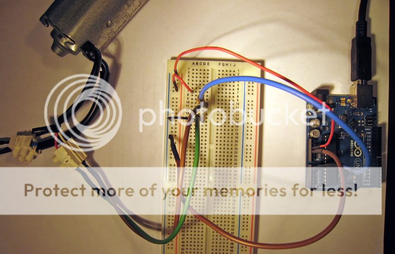
Could be one of the wires is a common ground or common +.

It also depends on whether the hall effect device is used as a speed controller or a position/velocity sensor? If it is used as a speed controller then you are just providing the bias voltage.

Sorry just going on memory here so terminology may be wrong it has been 20 years.
 
OP
OP
Snowbird

Snowbird

LIFE MEMBER
Apr 24, 2009
11,818
22,346
Liverpool.
Funster No
6,422
MH
Fifth wheel.
Exp
Since 11-05-2000
I asked for some help on the Arduino forums and IRC channel - Post here.

Helpful bunch but this was still a bit unclear. Here's a summary of what was said:

In desperation I took the unit carefully apart and inside there is a board with an Allegro A3321 connected to two wires only (red and white). It also has some sort of circuitry that looks to me like an SMT capacitor.

Now I just need to find the Allegro A3321 datasheet to be exactly sure of the spec. I also need to construct some kind of circuitry that maps 4.5V -> 0V and ~12V -> ~5V so I can read it with my Arduino without worrying about blowing it. I guess a reasonably high frequency MOSFET to keep it completely isolated is the way to go, agree?

Pictures:
MOTOR_OPEN.jpg


MOTOR_CIRCUIT_2.jpg


MOTOR_CIRCUIT_1.jpg


MOTOR_ALLEGRO_1_edit.jpg


MOTOR_BOARD_1.jpg


IMG_3477.jpg


IMG_3478.jpg
 
OP
OP
Snowbird

Snowbird

LIFE MEMBER
Apr 24, 2009
11,818
22,346
Liverpool.
Funster No
6,422
MH
Fifth wheel.
Exp
Since 11-05-2000
Hello funsters!

More progress to report. Thanks to the immense help of the kind folks on Arduino IRC and the Arduino forums (post HERE) it is now possible to read the precise position of the motors.

Diagram:
motor1.jpg

(Designed by sanelss & PWillard of the Arduino IRC)

Turns out that the hall sensor is supposed to be used as a current loop device. Everything in the dotted box labelled "Hall Module" above is part of the hall sensor circuit inside the motor itself and could not be changed. The hall sensor itself requires at least 4.5V to start working and seems to be designed to work at 12-14V (makes sense). The solution is to power the hall module directly from the car battery, use a comparator (LM393) to convert the voltage step between 3V and 9V to a nice digital 0V/12V step then connect the output to an optocoupler (OC1) which switches 0V/5V and which can be safely read by the Arduino.

As a bonus the resistor values can be set high to reduce power draw and an extra optocoupler (OC2) can be added to switch the whole circuit on and off so we are not wasting power when not reading the motors.

I have breadboarded this up first with an LED in place of OC1 and then with the actual optocoupler and this seems to work pretty well.

Here is an example code which counts the number of rising voltage pulses in 3 seconds then reports the result to a serial device (my computer). The "DATA" line should be connected to pin 2 on the Arduino Uno (which has interrupt 0 on it) and "ENABLE" should be pulled high to 5V. The variable "rotate" is declared volatile to keep it in RAM so that it can be quickly updated. Interrupt 0 is used to reduce the chance that we miss a pulse. More on Arduino Interrupts HERE.

Code:
Code:
volatile unsigned int rotate;

void setup()
 {
   Serial.begin(9600);
   attachInterrupt(0, rotate_inc, RISING);
   rotate = 0;
 }

void loop()
 {
     Serial.println(rotate,DEC);
     rotate=0;
     delay(3000);
 }

void rotate_inc()
 {
   rotate++;
 }
Eyeballing the rotation of the motor I estimated it took about 3 seconds for the geared output to rotate once. Going with the assumption that this motor is geared 210:1 (from the reference to the motor found in a previous post) we would expect at full speed to see about 210 reported.

Output:
Code:
0
0
0
86
240
240
240
241
240
240
185
41
0
0
0
The leading and trailing zeros have the motor detached from the battery. We see a peak of about 240 pulses in 3 seconds. Given the error in estimating how long the motor takes to rotate I think it is very likely this motor is geared 210:1 and that everything is functioning correctly.

Assuming we can control the motor down to the last blip of the hall sensor this gives us a resolution of 360/210 = 1.7 degrees. If we can control down to the nearest CHANGE of voltage we get a resolution of 360/420 = 0.9 degrees. Either of these cases look very promising.

Undoubtedly PWM will be needed to gain such fine control of the motor. Waiting for the Pololu motor controller board to arrive now to test this out!

Exciting times to come I'm sure...

Subscribers  do not see these advertisements


Wildman

Free Member
May 30, 2008
0
8,470
Ilfracombe, Devon
Funster No
2,913
MH
Amazon Ambassador
Exp
since 1967
Looking good. I trust you will be monitoring the wind generator to let the tracking system know when it is too windy and so leave the panel flat on the roof.:thumb::thumb:
 
Feb 27, 2011
14,741
76,015
UK
Funster No
15,452
MH
Self Build
Exp
Since 2005
Looking good Snowbird. Thanks for giving us such detailed reports. Makes for very interesting reading.
 
OP
OP
Snowbird

Snowbird

LIFE MEMBER
Apr 24, 2009
11,818
22,346
Liverpool.
Funster No
6,422
MH
Fifth wheel.
Exp
Since 11-05-2000
Monitoring wind is a good idea but no plans just yet.

Step 1 will just to be to get it working, if it's too windy, switch it off.

Subscribers  do not see these advertisements

 
Last edited:
OP
OP
Snowbird

Snowbird

LIFE MEMBER
Apr 24, 2009
11,818
22,346
Liverpool.
Funster No
6,422
MH
Fifth wheel.
Exp
Since 11-05-2000
I must admit I cannot take credit for all this techy stuff. My good pal Ste has done all the donkey work. I just supplied the motivation. We have both learned a lot from this project so far and am realy looking forward to the finished product. It has been a long haul for Ste but he has stuck it out when I would have thrown it in the bin. Must say one thing though am very impressed with his stamina :thumb:.
 

Geo

Trader - Funster
Jul 29, 2007
11,757
14,565
Mansfield,Notts
Funster No
35
MH
Autotrail Tracker FB
Exp
45 +years with breaks
Given the man Hrs put in,
Including schematics and breadboarding I expect this project to come in slightly under budget
@ 2.3 Million UK Pounds:thumb:
 
OP
OP
Snowbird

Snowbird

LIFE MEMBER
Apr 24, 2009
11,818
22,346
Liverpool.
Funster No
6,422
MH
Fifth wheel.
Exp
Since 11-05-2000
Given the man Hrs put in,
Including schematics and breadboarding I expect this project to come in slightly under budget
@ 2.3 Million UK Pounds:thumb:
Do you think its worth applying for some sort of government grant Geo. Seriously though, these projects would never be cost effective if it was not for the dedicated amateurs that gain pleasure and satisfaction from seeing if it can be done. With my old skool mechanical knowledge and his mathematical brain who knows what's in the pipeline next. Considering he didn't know how to use a soldering iron before this project am well impressed with the results.
Now then what about a solar powered steam engine :thumb:.

Subscribers  do not see these advertisements

 
OP
OP
Snowbird

Snowbird

LIFE MEMBER
Apr 24, 2009
11,818
22,346
Liverpool.
Funster No
6,422
MH
Fifth wheel.
Exp
Since 11-05-2000
The motor controller has arrived! It's still in its box at the moment but it's looking the part. I am pretty excited. I will have a closer look at it over the weekend and attempt to make the motor rotation sensor circuit using some perfboard.
 
OP
OP
Snowbird

Snowbird

LIFE MEMBER
Apr 24, 2009
11,818
22,346
Liverpool.
Funster No
6,422
MH
Fifth wheel.
Exp
Since 11-05-2000
This post is for the "technies" amongst you.

Once the electrical/mechanical issues are overcome (they are looking surmountable at this point) the next issue will be writing code that actually allows the Arduino to find the sun!

I've been searching the internet for such programs. There seem to be a few already existing for the Arduino, for example: www.cerebralmeltdown.com. There are many more written in C, C++, JavaScript, Java. You name it and somebody has implemented some algorithm in it.

The algorithms seem to vary from using tabulated data with a limited range of validity (<10 years) to using crude approximations with severe error propagation to full blown models of the earth-sun system.

I'm quite interested in understanding the very basics of these algorithms. Where do these algorithms come from? How do they work? What is their range of validity and how accurate are they? What's with all the arbitrary looking parameters?

I came across an Link Removed which I am planning to skim. I thought some of you might be interested in seeing it, it's just 58 pages and pretty introductory!

It also comes with a C++ implementation of their algorithm.
 
OP
OP
Snowbird

Snowbird

LIFE MEMBER
Apr 24, 2009
11,818
22,346
Liverpool.
Funster No
6,422
MH
Fifth wheel.
Exp
Since 11-05-2000
Skimming the paper it seems that it too resorts to huge amounts of unexplained tabulated data, this time in the form of "Earth Periodic Terms". I gather from the text this has something to do with the position of the earth in the Sun's frame, perhaps I can make some sense of it.

Do we have any astronimers in who could explain what goes into these formulas? Especially Eq (9) and (11).

I have also found another source (referenced by cerebralmeltdown). It is a book Astronomical Algorithms. Glancing through, a great deal of its ~400+ pages contain hints and tips regarding programming, rounding errors, debugging, trigonometry etc... and of course the customary hundred or so pages of tables. I'm hoping to get into some of the meat of it later in the week!

UPDATE:
The book is also referenced by the paper posted earlier. The table A4.2 Earth Periodic Terms is lifted directly from Astronomical Algorithms and apparently comes from the "French planetary theory VSOP87". I suppose deeply understanding these values (or calculating them myself) would require some accurate measurements and an understanding of that theory!

Subscribers  do not see these advertisements

 
Last edited:
OP
OP
Snowbird

Snowbird

LIFE MEMBER
Apr 24, 2009
11,818
22,346
Liverpool.
Funster No
6,422
MH
Fifth wheel.
Exp
Since 11-05-2000
Just to keep you up to date.

I have been looking through the cerebralmeltdown.com code and it is looking pretty good. Most of the solar tracker formulae are already built in and several units have been built and are performing well. I think this is the way we will go for performing the calculations. Head over there to have a look at some pictures and videos of the test equipment!

To deal with the inherent numerical inaccuracy of an 8-bit microcontroller they have used an implementation of the BigNumber library, which allows for arbitrary precision calculations to be performed. Not bad for a tiny little chip! This Arduino blows my mind.

Unfortunately, the library contained no trigonometric functions and so they had to implement all of these functions themselves. They did a pretty good job with Sin and Cos but were unable to implement ArcTan, ArcTan2 and ArcSin in a way that didn't lead the Arduino to crash.

I have been playing a little bit with the code over the weekend and have built a library utilising BigNumbers to calculate these functions to Arbitrary precision. The performance is quite good. If you'd like to read more check out this post on the cerebralmeltdown forums (by Ste... posting as Bob101): http://cerebralmeltdown.com/forum/index.php?topic=342.0

The second post has a pdf attached that explains some of the logic behind the implementation. :thumb:
 

hilldweller

LIFE MEMBER
Dec 5, 2008
605
36,109
Macclesfield
Funster No
5,089
MH
Zilch Mk1
Exp
From Aug 2007
Just to keep you up to date.

It's a good read. Though I can't believe how difficult you are making it.

How I see it.

You use 2 micro switches to elevate to 50 degrees, good enough.

You read the panel voltage, once you've got a bit, elevate and wag the panel to find the sun. Once every 15 mins, nudge the panel for a peak.

That's it. No maths. No GPS. No compass. Little debugging. No pain.

Simples.
 
Feb 27, 2011
14,741
76,015
UK
Funster No
15,452
MH
Self Build
Exp
Since 2005
Thanks for that. Looks really interesting. I have a few projects I need to start/finish but I will definately be looking at this again in the near future.
Great work.

Hilldweller. Sometimes seeing if you can is enough of a reason:thumb:

Subscribers  do not see these advertisements


hilldweller

LIFE MEMBER
Dec 5, 2008
605
36,109
Macclesfield
Funster No
5,089
MH
Zilch Mk1
Exp
From Aug 2007
Hilldweller. Sometimes seeing if you can is enough of a reason:thumb:

Yes of course it is, but over the last 30 years I've learned the KISS rule. Minimise everything as long as the goal is reached and you end up with a sweet system that can be fixed easily or modified when ( rather than if ) the goal posts move or the fork lift truck driver rams the machine.

If he does jump the incredible hurdles knitting that lot together excellent, if not he has a plan B.

As a matter of interest, here is (was) my world. "We bought this stacker but the electronics are shot, make us some new ones". It stacks boards coming off the the band saw into packs ready for banding. It's so exciting, so fulfilling I can appreciate Snowbird doing this.
 

Attachments

  • C1.jpg
    C1.jpg
    92.3 KB · Views: 43
  • c2.jpg
    c2.jpg
    95.7 KB · Views: 43

Langtoftlad

LIFE MEMBER
Apr 12, 2011
8,861
150,864
Langtoft, South Lincs
Funster No
16,024
MH
WildAx Aurora FB [PVC]
Exp
Since 2015
I've looked through this thread and doubt I understand 1% of what is being discussed technically but I do understand the thrill of the chase...

However, to achieve the objective surely the simplest solution is to have the solar mounted on a turntable which turns slowly at the speed the sun passes through the sky ???

May not get every last micro watt from your panel but surely pretty close.
 

Wildman

Free Member
May 30, 2008
0
8,470
Ilfracombe, Devon
Funster No
2,913
MH
Amazon Ambassador
Exp
since 1967
It's a good read. Though I can't believe how difficult you are making it.

How I see it.

You use 2 micro switches to elevate to 50 degrees, good enough.

You read the panel voltage, once you've got a bit, elevate and wag the panel to find the sun. Once every 15 mins, nudge the panel for a peak.

That's it. No maths. No GPS. No compass. Little debugging. No pain.

Simples.
actualy Brian once an hour is sufficient and a simple basic program could do the reading and moving.

Subscribers  do not see these advertisements


hilldweller

LIFE MEMBER
Dec 5, 2008
605
36,109
Macclesfield
Funster No
5,089
MH
Zilch Mk1
Exp
From Aug 2007
However, to achieve the objective surely the simplest solution is to have the solar mounted on a turntable which turns slowly at the speed the sun passes through the sky ???

That is it. What we are negotiating is how to determine this speed. And how to get the panel in the start position at dawn bearing in mind the van can be parked facing any direction.

Snowbird's GPS + Compass has the potential for 0.1 deg accuracy anywhere in the world.

My "turn it to get highest voltage" is a few degrees of accuracy. Mine may go pear shaped with a lot of clouds. I have a plan B of a detector consisting of 8 photo diodes in a ring, this could detect the brightest part of the sky silently the when sure drive the panel to the same heading.

I wonder if the moon or local lighting could be used at night !!
 
Feb 27, 2011
14,741
76,015
UK
Funster No
15,452
MH
Self Build
Exp
Since 2005
Yes of course it is, but over the last 30 years I've learned the KISS rule. Minimise everything as long as the goal is reached and you end up with a sweet system that can be fixed easily or modified when ( rather than if ) the goal posts move or the fork lift truck driver rams the machine.

If he does jump the incredible hurdles knitting that lot together excellent, if not he has a plan B.

Make your mind up:ROFLMAO::ROFLMAO::ROFLMAO:

Back in Broken Link Removed I mentioned my simple discrete component method and Broken Link Removed you say
Hilldweller said:
Doing it The Olde Way makes no sense in the 21st century.

I suggest simple you say microcontroller makes more sense.
Snowbird does the microcontroller method fully and it is too complicated.

Only Joshing Brian I know what you mean :winky:::bigsmile:

I have to say I love this project and am impressed with his motivation:thumb:
 

Langtoftlad

LIFE MEMBER
Apr 12, 2011
8,861
150,864
Langtoft, South Lincs
Funster No
16,024
MH
WildAx Aurora FB [PVC]
Exp
Since 2015
That is it. What we are negotiating is how to determine this speed. And how to get the panel in the start position at dawn bearing in mind the van can be parked facing any direction!

Kinda reminds me of the apocryphal story about how NASA invested millions during the 60's Space Race to develop a Biro which would write in a vacuum & upside down...


...the Russians just took a pencil :Cool: !

[The Fisher Space Pen is pretty cool though, even today]

Subscribers  do not see these advertisements


Join us or log in to post a reply.

To join in you must be a member of MotorhomeFun

Join MotorhomeFun

Join us, it quick and easy!

Log in

Already a member? Log in here.

Latest journal entries

Funsters who are viewing this thread

Back
Top