Any advice on a wiring diagram I've made?

CamperJack

Free Member
Joined
Oct 11, 2019
Posts
926
Likes collected
3,540
Location
Cheshire
Funster No
65,289
MH
Converting a Van
Exp
I'm a Total Newbie!
This has taken quite a bit of time. But it has been worth it because I feel a little more confident.

The image below is a wiring diagram I have drawn. I haven't bought an inverter yet, and I also plan to install a mains battery charger but not just yet.

I welcome any any all comments on this from members. I'd love to hear if you'd do anything differently or if you think I've missed something!

I need to include a fuse on the positive terminal of the battery. Would a ceramic 200A fuse be appropriate? (Like this: https://tinyurl.com/200AFuse)
Should all loads on the battery be mounted to the same terminal?


Thank you for all the help so far and thanks for looking. (y)

33. Wiring Diagram.jpg


1. 500W Solar Panels in via a 6mm² 70A MC4 extension cable. This goes into a Epever 40A Solar Charge Controler, first via a 40A fuse and a kill switch.

2. This is connected to the two 110 ah batteries, via 10mm² 70A wire through another kill switch.

3. The two 110 ah batteries are connected in parallel ( + to +, - to -) using 35mm² wire.

4. The power will be supplied to 12v appliances via a Blue Sea ST 5026 Fuse Box, which is rated at upto 30 amps per circuit and 100 amps for the entire block.
Power to the fuse box via a positive 35mm² 240A wire and negative back to the battery negative. Kill switch on +tive wire between battery and fuse box.

5. Power to 12v appliances (lights, 12v sockets, USB chargers and fridge etc) from this fuse box, with an appropriate fuse inserted and using 3mm² 33A wire.

6. Charging of leisure batteries via a Stirling 30A Battery To Battery Charger. Connection from starter battery, first via a 30A fuse and then a kill switch into the positive terminal of the B2B using 6mm² 53A wire. Negetive back to starter battery. Then power out via same size of wire and another 30A fuse to leisure batteries.
 
Quick questions, unless I'm missing something:

What about a charge to your starter battery from Solar ?

No option to charge either batteries on EHU?
 
Quick questions, unless I'm missing something:

What about a charge to your starter battery from Solar ?

No option to charge either batteries on EHU?

Hi Nasher.

Thanks for the reply!

The leisure batteries will be charged on EHU when I buy and fit a mains battery charger. This one was kindly recommended to me my Hilldweller from this forum. (This is the charger: <Broken link removed>)

To be honest the idea of charging the batteries via the solar or EHU hadn't crossed my mind. How is this most commonly done?

If the starter battery fails while at home (and it may well do as it isn't going anywhere for a while) we have an additional battery charger in the garage. :giggle:

Probably not a bad idea to hook it up some time soon actually.
 
have a look at youtube and the loads of videos and information. youre doing the right thing by asking for advice but that doesnt stop you going out and searching for examples and information. Greg Virgoe has some extensive videos on youtube
 
Have a look at the Battery Master from Vanbitz (discount for funsters)

It trickle charges the cab battery if the leisure side has a higher voltage

So it will trickle charge from your solar & EHU

Simple to fit

Subscribers  do not see these advertisements

 
Good start, I know how hard it is to lay out a schematic. I usually forget something so end up with a load of amendments and crossed out links.

electricalcarservices.com sell loads of useful busbars, fuseblocks,terminals etc.
 
You don't need a switch inline with the output of the solar regulator as most regulators require the battery to be connected before the panels to set the output voltage.
As you rarely need to disconnect the solar panels you could just put a 40 amp blade maxi-fuse and do away with the switch & just pull the fuse to disconnect.
The fuses for your B2B probably need to be 40 amp, the fuse is to protect the cable under fault conditions you don't want it blowing in normal use.
 
probably too many kill switches you only need a fuse close to the battery on the wire to you controler and unless the epever is different i doubt youll get 10mm cable into the tereminals
 
Possibly not important in the scheme ifthings but I think sterling recommended linking the leisure and start battery negatives rather than relying on a chassis connection.. Check their instructions..
Andy..
 
Have a look at the Battery Master from Vanbitz (discount for funsters)

It trickle charges the cab battery if the leisure side has a higher voltage

So it will trickle charge from your solar & EHU

Simple to fit

Looks like a good piece of kit. I might get one! Thanks. :giggle:

Good start, I know how hard it is to lay out a schematic. I usually forget something so end up with a load of amendments and crossed out links.

electricalcarservices.com sell loads of useful busbars, fuseblocks,terminals etc.

This must be version five or six. I have a messy one sat on my desk, and made a neater one to share on here. (y)

The fuses for your B2B probably need to be 40 amp, the fuse is to protect the cable under fault conditions you don't want it blowing in normal use.

I thought the same thing, and on one of my original diagrams I put in a 40 amp fuse. But I had seen another person's diagram with a 30A fuse in it. I've just looked into it again and in Stirling's instruction book it actually says 40A. So I'll make the change. Thanks a lot for the help! :giggle:

unless the epever is different i doubt youll get 10mm cable into the tereminals

Thanks for taking the time to reply to me! I've just checked it out again to be sure. It must be different. This is the chart in the instruction book. Looks like I could use upto 16mm². Do you think I should up it to 16mm²?

solar charge controler battery wire size.png


Might be worth putting in a positive and negative terminal post so only the two leads going to the batt.


So would that be a fuse on the battery +tive terminal, big 16mm² wire to a post on one of these, and then run the wires to the fuse block, charge controller, inverter etc from that? Would probably make things neater if I've understood the purpose of them correctly? Thanks a lot for helping.
 
Possibly not important in the scheme ifthings but I think sterling recommended linking the leisure and start battery negatives rather than relying on a chassis connection.. Check their instructions..
Andy..

That should be quite an easy thing to do anyway. I'll run a negative in the same gap trunking as the positive.
 
Quick question. Is the kill switch between the starter battery and the b2b important or can you just remove the fuse? There’s no kill switch on the diagram but should there be?

Fuse type in use below.

85E499A8-F2A1-498D-ADCB-78602A75BA60.jpeg
 
You could use 12v circuit breakers, then you wouldn't need switches as well. I would fit a fuse between controller and batteries and batteries and inverter unless the wires are really short.

Subscribers  do not see these advertisements

 
You could use 12v circuit breakers, then you wouldn't need switches as well. I would fit a fuse between controller and batteries and batteries and inverter unless the wires are really short.

So if using these fuses I will need a switch?
 
No just press the test button and they disconnect, push the lever back to switch back on.

Thanks for replying again! 🙂

Sorry. I’m not understanding you. I have these fuses, as pictured above. I don’t have breakers. There is no tester button?

What I want to know is is a switch needed between the starter battery and the b2b?

I have it in my head that I’ll need to switch it off at a kill switch to work on the system in the future. But would I simply disconnect the fuse (pictured) instead of having the kill switch, or is that unsafe to do?
 
Perfectly safe just to remove the fuse. If youre only doing it occassionally its not a problem. If you have to do it often a switch or circuit breaker is just more convenient.
 
As we can't judge cable lengths looking at the diagram I'd say the B2B fuse may be better at the battery end as its already got one on the feed from the starter battery. I'd be tempted to put one at either end myself if its a long run.

I'd also put the inverter fuse closer to the battery rather than at the inverter end . You want fuses closest to the power to protect the cable

Also a mega fuse or circuit breaker on the 35mm cable to the fusebox, could lose the kill switch then. Depends on cable lengths, if all short runs not running under or through anything then may get away with it on some.

If you have fuses then you don't really need 5 kill switches as well. Its easy to disconnect a battery lead or fuse. Just more expense and thing to find a place for.

I only have one kill switch and thats for the inverter as they can draw power on standby so turn it off.

6mm sounds small for the B2B cable, its more about voltage drop than amps so depends how far from the leisure battery its going to be.

Subscribers  do not see these advertisements

 
Perfectly safe just to remove the fuse. If youre only doing it occassionally its not a problem. If you have to do it often a switch or circuit breaker is just more convenient.

Thanks for taking the time to help me! It’s much appreciated. 👍🙂
 
As we can't judge cable lengths looking at the diagram I'd say the B2B fuse may be better at the battery end as its already got one on the feed from the starter battery. I'd be tempted to put one at either end myself if its a long run.

I'd also put the inverter fuse closer to the battery rather than at the inverter end . You want fuses closest to the power to protect the cable

Also a mega fuse or circuit breaker on the 35mm cable to the fusebox, could lose the kill switch then. Depends on cable lengths, if all short runs not running under or through anything then may get away with it on some.

If you have fuses then you don't really need 5 kill switches as well. Its easy to disconnect a battery lead or fuse. Just more expense and thing to find a place for.

I only have one kill switch and thats for the inverter as they can draw power on standby so turn it off.

6mm sounds small for the B2B cable, its more about voltage drop than amps so depends how far from the leisure battery its going to be.

The batteries are installed and wired together now. The 12v fuse panel is already connected via the kill switch. The b2b is installed without a switch, but I did put in two fuses.

I ended up increasing the size of the cable for the b2b to 10mm2 - this is in line with the instruction manual for the length of cable run. I measured it to be sure.

For the b2b there is a 40A fuse about 15cm from the positive terminal of the starter battery. It then runs into the positive in of the unit. Also the negetive terminal of the starter battery is connected via 10mm2 cable to the negetive connection of the unit. Positive out is then connected to the positive terminal of the leisure battery via a 40A fuse on a short run of less than 20cm.

I’ll be sure to put the inverter fuse closer to the battery. Thank you.

Thanks a lot for a detailed reply. Very helpful! 👍👍
 
When I switched the engine on my Dad reported that it beeped. Not sure if it was the b2b for something in the cab. The light showing bulk charging was showing at first, then a few minutes later it went to absorption light. It stayed there for 10 minutes until I turned the engine off. A fan in the unit was running and got louder after the engine was turned off. Then the fan stopped after a few minutes.

I think it’s working?? 🤔

036E4BD6-13D5-4BFE-A34E-5AD34EF0F8DE.jpeg
 

Attachments

  • 9134FE1C-D50E-4DEE-8481-8423F32CB6B6.jpeg
    9134FE1C-D50E-4DEE-8481-8423F32CB6B6.jpeg
    112.3 KB · Views: 35
  • 0F79D8D4-48AB-4C6D-A479-337921359B22.jpeg
    0F79D8D4-48AB-4C6D-A479-337921359B22.jpeg
    112.3 KB · Views: 30
Hi guys. I’m hoping to fit the solar panels tomorrow. I’ve already made the wires to connect the charge controller to the batteries via the fuse etc.

Tomorrow I’ll be mounting the panels to the roof and connecting to the controller.

I want to wire in parallel (so positive to positive) and negative to negative).

However the positive wires on the panels are both male mc4 and the negative wires are both female. So obviously they don’t fit.

Would the correct thing to do be to make a section of cable with a female mc4 at each end to link the two positive cables from the panels together? And make a wire with two male ends to connect the negative solar panel cables?

Have I got that right and have others had to do this.

Cheers in advance!

Jack.
 
I cut the mc4’s, bring the cables in via glands, and connect each panel to its own fuse in a combiner box. I use gPV 10x38 fuses in din holders. From the box, up the cable to the charger. If your panel ISC is 8-9 A, use a 10A fuse, but do not exceed system max fuse 15A.

Subscribers  do not see these advertisements

 
Thanks, Raul. I wonder what others have done?
 
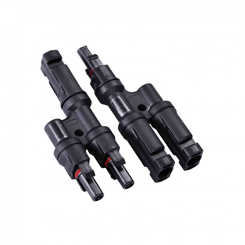
Rain stopped play today. But I have bought some of these.

multi-contact-mc4-21-connectors-for-a-4-6mm-cable.jpg
 

Join us or log in to post a reply.

To join in you must be a member of MotorhomeFun

Join MotorhomeFun

Join us, it quick and easy!

Log in

Already a member? Log in here.

Latest journal entries

Back
Top