Swift split charge relay and habitation relay location help (1 Viewer)

Aug 11, 2019
73
51
Funster No
63,159
MH
Swift Kon Tiki 679
Exp
2018
Hello everyone.

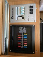
I have two 110 Gel batteries, 4 Kw Peak pure sin wave inverter with auto cut over to sockets, 300 watt of solar with Victron Bluetooth Controller, Victron Mains battery charger, and have just bought a victron 30amp B2B charger (I may upgrade to dual if required and funds allow)

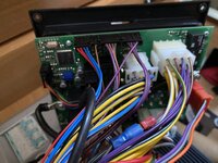
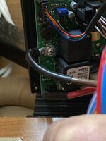
For part of the B2B installation I would like to:-

Remove the OEM split charge but keep 12v feed to Fridge
disable or put manual switch on habitation lights/pumps etc so van electrics can be used with engine running.

Can anyone help me locate where they are on a 2009 Swift Kon Tiki 669.

thanks
 
OP
OP
Largejj
Aug 11, 2019
73
51
Funster No
63,159
MH
Swift Kon Tiki 679
Exp
2018
Update have now installed the B2B but still cannot find the split charge or habitation delay so I can disable them.

Any help would be appreciated :)
 

hilldweller

LIFE MEMBER
Dec 5, 2008
605
36,109
Macclesfield
Funster No
5,089
MH
Zilch Mk1
Exp
From Aug 2007
A common place for the split charge relay is next to the starter battery. Look for a relay that looks like it does not belong there.

Subscribers  do not see these advertisements

 
OP
OP
Largejj
Aug 11, 2019
73
51
Funster No
63,159
MH
Swift Kon Tiki 679
Exp
2018
Thanks is for your help.

There is nothing near the main starter battery.

I have read it could be near the B pillar on drivers side.

I’m surprised i’m the only one with this issue.

A common place for the split charge relay is next to the starter battery. Look for a relay that looks like it does not belong there.
 
Mar 15, 2019
518
933
Funster No
59,148
MH
AutoCruise Stardream
Exp
Newbie April 2019
On our Autocruise the split charge is built into the control box behind the drivers seat, it just has a 50a fused feed direct from the battery. So not all have the seperare relay you are looking for.

On ours I'd simply take the fuse off if I wanted to add a B2B.

Do you know what make/model your electric controller box is?
 
OP
OP
Largejj
Aug 11, 2019
73
51
Funster No
63,159
MH
Swift Kon Tiki 679
Exp
2018
Thanks for reply the panel is a nordelettronica ne222. Have been using the B2B with split charger still in place but it’s not performing properly until I remove the split charge feed.

Subscribers  do not see these advertisements

 
Last edited:
OP
OP
Largejj
Aug 11, 2019
73
51
Funster No
63,159
MH
Swift Kon Tiki 679
Exp
2018
Ok thanks have sent them a message.
 
Apr 27, 2016
6,873
7,994
Manchester
Funster No
42,762
MH
A class Hymer
Exp
Since the 80s
The NE222 is the control panel, is this connected to a control/fuse box located in a less obvious place? That's where the relays will be. Any autocruise owners know where it's likely to be? If you find it, what model of control box is it?

Subscribers  do not see these advertisements

 
OP
OP
Largejj
Aug 11, 2019
73
51
Funster No
63,159
MH
Swift Kon Tiki 679
Exp
2018
The fuse panel is under the rear seat. Cannot see any relays unless they are hidden underneath? I suspect there should be three (1) fridge (2) split charge (3) Habitation relay?
 

Attachments

  • E204C391-5BFC-4092-B0FB-042542833E60.jpeg
    E204C391-5BFC-4092-B0FB-042542833E60.jpeg
    145.2 KB · Views: 171

BDM

Aug 17, 2013
155
198
Norwich
Funster No
27,556
MH
544
Exp
Since 2008
The relays are on a pcb on the backside of the fuse panel. Remove it and you will see them.
 
Apr 27, 2016
6,873
7,994
Manchester
Funster No
42,762
MH
A class Hymer
Exp
Since the 80s
I'd guess that the fuse box, when the screws are removed, will be a box with relays and other connections to the batteries. Anyone who's taken one out will know, but I haven't.
Edit: BDM's post shows the back of it
 
Jan 28, 2008
10,117
18,382
Dovercourt, Harwich, UK
Funster No
1,353
MH
Renalt burstner
Exp
7 years campers before that
moden motorhomes seldom have a seperate relay its now part of the controll system and as shown part of the pcb
 

BDM

Aug 17, 2013
155
198
Norwich
Funster No
27,556
MH
544
Exp
Since 2008
NE148 wiring diag..jpg


This is the 148, not the 221 but gives you the idea.

Subscribers  do not see these advertisements

 
Apr 27, 2016
6,873
7,994
Manchester
Funster No
42,762
MH
A class Hymer
Exp
Since the 80s
Update have now installed the B2B but still cannot find the split charge or habitation delay so I can disable them.
Looking at the photo in post #12 BDM I'd guess that the split charge relay is the black square, top right. The black square below I'd guess is the habitation relay.

The feeds from the two batteries, and the single common negative, go to the PCB by double wires, to screw terminals.

The negative screw terminal is on the left edge in the middle, just below the red 4-way connector.
The screw terminal for the starter battery positive I guess is top right, just above what I think is the split charge relay.
The screw terminal for the leisure battery I guess is just to the right of what I think is the habitation relay.
By measuring the exact voltage of the starter and leisure batteries, and comparing to the voltages of the screw terminals you should be able to confirm this, or prove my guesses to be wrong.

Quite how you disable the split charge relay I'm not sure. You can't just remove the screw terminals because that will stop many other functions working. The alternative of removing the D+ signal (the signal that causes the split charge relay to close) won't work either, because other things including the habitation relay need that signal to work properly.

If the split charge relay is not soldered to the PCB and is in a socket, you could simply unplug it. If it's soldered in, then the sort of person that can replace a faulty relay would be able to unsolder the relay to remove it.

Yes, it's a bit complicated, if someone has a simpler solution I'm sure they'll say.
 

BDM

Aug 17, 2013
155
198
Norwich
Funster No
27,556
MH
544
Exp
Since 2008
I have actually done this on my NE148 board. The relays are soldered and failing to remove the relay I took a pair of pliers and disabled it, or to put it another way, I ripped the casing off and pulled the innards out! Make sure you get the correct relay though! I cannot remember how I figured which one to go at. There has been chatter about removing a jumper or a solder connection on the pcb but these were not options on my board. The NE 221 is newer I would guess so may have an easier option to disable, Delta conversions hopefully can advise.
 
Apr 27, 2016
6,873
7,994
Manchester
Funster No
42,762
MH
A class Hymer
Exp
Since the 80s
There has been chatter about removing a jumper or a solder connection on the pcb but these were not options on my board.
If I had the board in front of me, I'd be looking at the relay coil terminals. The D+signal goes to the coil, so I'd be looking for a jumper or solder connection. If not, maybe removing a component that carries the signal. Or if there's nothing like that, then using a Dremel on the pcb track to the coil.

Subscribers  do not see these advertisements

 
OP
OP
Largejj
Aug 11, 2019
73
51
Funster No
63,159
MH
Swift Kon Tiki 679
Exp
2018
Thank for replies. I will try and remove the fuse board later and photograph. Ideally would like to modify the split charge relay with a switch for the coil so I could reinstate if the b2b ever failed. Same for habitation relay. Just returned on a trip back from wales and the habitation relay appears not to be working as step did not auto retract and lights/pump stayed on. would like to fix this before I modify anything!
 
Jul 6, 2016
1,547
1,264
West Sussex
Funster No
43,954
MH
Carthago Chic A clas
Exp
Since 1990
This thread might help:


Ok, it's a different system but same principles apply. Basically, the leisure batteries are isolated from the distrubution box whilst the alternator is charging. But first check the effect on other services like step, fridge etc (with engine running) by manually disconnecting the feed from leisure batteries to distribution box. Similarly, then disconnect the feed from starter battery to distribution box and note the effect on other services. Sometimes the fridge is powered from the leisure batteries and sometimes from the starter battery.

Once you've established the effect on other services by the "cause and effect" method, you'll be in a better position to understand the workings of the system so you can effectively bypass the existing split-charge relay by inserting a "normally closed" relay in an appropriate part of the wiring network.

You mention the installed B2B isn't working properly. You could test the B2B by removing the feed from LB's to distribution box. If there is no improvement then check the wiring of the B2B.

Subscribers  do not see these advertisements

 
Apr 27, 2016
6,873
7,994
Manchester
Funster No
42,762
MH
A class Hymer
Exp
Since the 80s
Ideally would like to modify the split charge relay with a switch for the coil so I could reinstate if the b2b ever failed.
There may be a 'jumper' on the circuit board, to carry the D+ signal to the split charge relay. You could remove it and put in a couple of wires and a switch, to enable or disable the split charge relay.
 
OP
OP
Largejj
Aug 11, 2019
73
51
Funster No
63,159
MH
Swift Kon Tiki 679
Exp
2018
Just had this reply from Delta


Thanks for your message.


The NE221 and NE222 system isn’t designed to be able to use a DC-DC charger.


There is no way to disable the split charge system on the fuse board, other than having the relay removed completely and the PCB modified to accept this change.


The DC-DC charger you have installed may be responsible for the van battery voltage being incorrectly displayed.


Again, with regard to modifying the fuse board to try and make certain components run via a DC-DC charger in a system that isn’t really capable of having a DC-DC as part of the system isn’t going to be possible as the fuse board has on-board software that runs the system that can’t be altered.


Sorry I can’t be of more assistance but it is just a matter of some of the modern equipment you’re installing just isn’t compatible with a system designed over 10 years ago.


Regards,

Paul


Paul Bowers

Technical Support and Sales

Nordelettronica UK Sales
 

BDM

Aug 17, 2013
155
198
Norwich
Funster No
27,556
MH
544
Exp
Since 2008
I suggest you ask Paul to send you the Instruction book and wiring diagram. That, along with all the responses above, should give you the information you need.

Subscribers  do not see these advertisements

 
Jul 6, 2016
1,547
1,264
West Sussex
Funster No
43,954
MH
Carthago Chic A clas
Exp
Since 1990
So, what is this problem you have with the van battery voltage being displayed incorrectly ? Does the voltage differ compared with using a multimeter across the LB's ?
 
OP
OP
Largejj
Aug 11, 2019
73
51
Funster No
63,159
MH
Swift Kon Tiki 679
Exp
2018
The control panel has recently started to report 0v for engine battery even though voltage is good and no issues. At the same time the habitation relay has started to not cut out so the step stays out and lights stay on. This is intermittent so think is wiring issue ?
 
Jul 6, 2016
1,547
1,264
West Sussex
Funster No
43,954
MH
Carthago Chic A clas
Exp
Since 1990
The control panel has recently started to report 0v for engine battery even though voltage is good and no issues. At the same time the habitation relay has started to not cut out so the step stays out and lights stay on. This is intermittent so think is wiring issue ?

Are you saying the above two issues occurred after you installed the B2B ? I guess all the other functions on the control panel are working as normal.

What size B2B have you installed and what size is your leisure battery bank. I assume the B2B is fitted directly between the starter battery and LB's.

Notwithstanding what Nordelettronica say, there is a workaround as discussed above.

Subscribers  do not see these advertisements

 
Apr 27, 2016
6,873
7,994
Manchester
Funster No
42,762
MH
A class Hymer
Exp
Since the 80s
Here's a suggestion. You could fit a changeover relay in the feed from the leisure battery. Use this to disconnect the leisure battery from the NE221 fuseboard entirely when the engine is running. Use the same relay to connect the leisure battery to the B2B when the engine is running.

Since the NE221 fuseboard has the quirkily British function of disconnecting everything from the leisure battery when the engine is running, the disconnection won't matter at all. But even if it did, for example for power to retract the step or run the heater, the starter battery will connect to the (disconnected) leisure battery supply, and provide power for anything required while the engine is running.

So fit a high power changeover relay: connect Common (COM) to the leisure battery, Normally Closed (NC) to the NE221 leisure battery terminal, and Normally Open (NO) to the B2B leisure battery output. The coil terminals: the positive to the D+ signal from the alternator, the negative to ground.

The leisure battery will be charged from the B2B when the engine is running, and will be switched back to the fuseboard when the engine stops.
 
OP
OP
Largejj
Aug 11, 2019
73
51
Funster No
63,159
MH
Swift Kon Tiki 679
Exp
2018
I spoke with ApulJack engineering today and they said:-

When a B2B is fitted, many companies/engineers will disable the D+ feed to your fuseboard, which is the signal feed from your alternator that triggers your step retraction, hab relay and fridge power change over. It is likely that this is the case with your set up.

You can locate the D+ feed on block JP4 on your fuseboard, pin 6. If this wire is missing/not intact along its length, then these functions will not work.

If you would like, you can send your fuseboard in for us to disable the relay which controls the split charge. We would charge 1 hour’s labour for this work, plus return shipping.


I have power on pin 6 JP4 with ignition but still got same issues. Also the voltmeter on the control panel for engine battery says 0v and this would not need the D+ igntion feed as the volt meter works without.

So either I need to get the board repaired or there is a feed issue from the cab electrics.

any ideas ?
 
OP
OP
Largejj
Aug 11, 2019
73
51
Funster No
63,159
MH
Swift Kon Tiki 679
Exp
2018
Does anyone have a wiring diagram with fuse feeds for the NE222? The main brown wire is 13.1v (leisure battery) and red one is 0v with ignition off and on.
I assume the large red wire should be vehicle battery permanent live. trying to find where this is supplied from to check fuse etc.

Subscribers  do not see these advertisements


Attachments

  • 25FA2536-1322-4EEB-96BC-2075ECC1BCE4.jpeg
    25FA2536-1322-4EEB-96BC-2075ECC1BCE4.jpeg
    484.2 KB · Views: 72
  • 645CB954-D1E2-49FC-9F27-B829FFE9FBF9.jpeg
    645CB954-D1E2-49FC-9F27-B829FFE9FBF9.jpeg
    365.8 KB · Views: 76
  • 661CDE15-F5B9-493E-8AA3-E8F89DCE78F6.jpeg
    661CDE15-F5B9-493E-8AA3-E8F89DCE78F6.jpeg
    560.4 KB · Views: 78

Join us or log in to post a reply.

To join in you must be a member of MotorhomeFun

Join MotorhomeFun

Join us, it quick and easy!

Log in

Already a member? Log in here.

Latest journal entries

Funsters who are viewing this thread

Back
Top