Some quick silly questions.

Joined
Jan 11, 2018
Posts
1,235
Likes collected
1,470
Location
Malvern Link, Malvern, UK
Funster No
51,943
MH
Chausson Welcome 85
Exp
Since 2018
Planning an install on my motorhome.
I have a 2 battery , PWM 20A controller.

1) Once the mounting brackets are fixed to the panel I am planning to glue the panel to the motorhome roof using Sikaflex 252i. Is this a good solution?(reason is to avoid holes in the roof.
2) Most panels come with a relatively short pair of leads with MC4 connectors moulded on. Are there any cable glands that an MC4 can pass through or do you always end up cutting them off? Or do you connect underneath the panel with MC4's which have been fitted to the upcoming cable from the interior of the motorhome?, These MC4's are not moulded on.
3) What edge length of panel do you need to have got before you need a centre mounting in between the corners? Thinking here of panel flex if it's say 1.2m long.
4) I have a CBE516 charger wired to a CBE DS304-TR distribution box. I am planning to wire the 2 outputs from the regulator , one to terminal B1 and one to terminal B2 on the distribution box. These are connected to the cab and leisure batteries and most importantly are easy to access at the foot of the bed where the panel wires will descend down to. If the EHU is on and the CBE 516 is running the voltage at both of these terminals will be around 14v so the solar regulator will shut off energy from the panel.
An image of my wiring diagramme is attached , you can see the CBE distribution box roughly in the middle of the picture.
Does this seem to be a good plan? It certainly vastly simplifies wiring.

TIA
wiring diag.jpg
 
I can't see why not although on our system that is CBE I just went straight to the leisure batteries as they were close, I then used a battery master connected to the terminals that you are proposing to use to keep the starter battery charged.

Martin
 
I can't see why not although on our system that is CBE I just went straight to the leisure batteries as they were close, I then used a battery master connected to the terminals that you are proposing to use to keep the starter battery charged.

Martin
Thank you, yes, I understand that. However the regulator I have has 2 outputs so I plan to connect directly to the can and leisure batteries so hopefully no need for one.
The regulator does prioritize the first output so maybe that should go to the leisure battery.
 
Firstly, I would fit MC4 extension cables to the tails on the panels, then run the cables through the glands on the roof entry unit direct to the controller.
Depending how you intend to use the van, hook up, on off or winter or summer you will need to consider the voltage threshold from the solar controller before it starts charging battery B, you may find that it is quite high and may not charge the van battery as you expect, we experienced this on our Rapido fitted CBE system and as advised above fitted a CBE battery master which solved the problem.
Cheers
Ed
 
Thank you Sheddy but I wanted to know if you can get an MC4 through most glands to avoid cutting it off and destroying all that integrity. What are your thoughts?
Is there a gland that can do this ?

TIA

Subscribers  do not see these advertisements

 
You need to be running the Cables from the Solar panel to the controller not the reverse. Do you need an MC4 connectors on the solar control unit? They are usually just termination connections. The extension cables have single MC4 plugs / sockets fitted with cable to pass through a gland before running direct to the controller.
Cheers
Ed
 
Planning an install on my motorhome.
I have a 2 battery , PWM 20A controller.

1) Once the mounting brackets are fixed to the panel I am planning to glue the panel to the motorhome roof using Sikaflex 252i. Is this a good solution?(reason is to avoid holes in the roof.
It depends what your roof structure is and whether the outer skin is actually attached fully to the inner and not just 'covering' it, it is know that some MHs have a 'floating' roof panel to allow for expansion etc, in which case it would be better to screw it and then seal round to keep water out.

2) Most panels come with a relatively short pair of leads with MC4 connectors moulded on. Are there any cable glands that an MC4 can pass through or do you always end up cutting them off? Or do you connect underneath the panel with MC4's which have been fitted to the upcoming cable from the interior of the motorhome?, These MC4's are not moulded on.
You wont AFAIK find a gland that will allow the MC4 connectors to pass through. You can cut them off/remove them but then you are left with having to join the long cable to them in some way to the panels so you might as well use the existing MC4s and put 'mating' ones on the cable you intend to run down to the controller. When I did my install I did the latter and hid the cabling in electrical clip conduit to keep it neat and ensure that the MC4s were kept out of the weather.

3) What edge length of panel do you need to have got before you need a centre mounting in between the corners? Thinking here of panel flex if it's say 1.2m long.
I fitted semi-flexible ones to my camper so didn't have to worry about this but if you are going for rigid panels you could do what another member did (Wissel) who stuck square alloy tubing to the roof and then fixed the panels to that, by doing this you do away with the expense of buying the plastic or alloy 'feet' (which aren't always cheap) and can put extra supports bars in the centre.


4) I have a CBE516 charger wired to a CBE DS304-TR distribution box. I am planning to wire the 2 outputs from the regulator , one to terminal B1 and one to terminal B2 on the distribution box. These are connected to the cab and leisure batteries and most importantly are easy to access at the foot of the bed where the panel wires will descend down to. If the EHU is on and the CBE 516 is running the voltage at both of these terminals will be around 14v so the solar regulator will shut off energy from the panel.
Sorry, I don't know anything about CBE wiring.
 
You need to be running the Cables from the Solar panel to the controller not the reverse.
Eh? Does it matter whether you feed them up or down???? ?
 
You can get mc4 connectors and anything else electrical from 12volt planet online they are easy to fit, I shortened mine and fitted bigger cable from the panel to the controller
 
You can get mc4 connectors and anything else electrical from 12volt planet online they are easy to fit, I shortened mine and fitted bigger cable from the panel to the controller
Thank you, I was asking to find out if anybody had used a cable gland which could pass an MC4 through it, avoiding cutting them off. The answer I think is No.
However, fitted correctly (ie. soldered and crimped etc.) I dont think there will be a problem.

A lot of the cheaper panels only supply 1m of lead which is very stingy and I don't really want to have to have mating MC4's underneath the panel in the weather if I can avoid it.
 
I don't really want to have to have mating MC4's underneath the panel in the weather if I can avoid it.
They're exposed on my home installation and have been for the past 8 years. They're designed for the job. If you don't want them on the roof wire direct from the panel with longer leads. MC4s do however offer the opportunity for a T connection if you add panels later. Don't solder. Correct crimping avoids insulation damage and retains flexibility where cables are subject to vibration. Keep connections clear of the roof (and pools of water) by keeping your first connection under the panel & zip tied to the panel mounting. I use 3x2 alloy angle as a mount. 6" lengths with a central one each side for longer panels (over 2 feet).
 
They come with rubber grommets and once the gland is tightened there fully waterproof. I cut the cables back to 6” to keep them
Off the roof

Subscribers  do not see these advertisements

 
The CBE mains charger has an additional signal wire to a relay on the DS board which triggers a trickle charge to the vehicle battery (B1).

So connecting the output from the solar regulator to +B1 is unlikely to work unless your DS board has been configured differently.

This is discussed in some depth on the outandaboutlive forum https://forums.outandaboutlive.co.uk/forums/Motorhomes/Motorhome-Matters/CBE-and-solar/53233/

Thank you. I know the CBE516 when connected via the EHU charges both batteries, with the cab battery only getting a 2A charge with the leisure battery presumably getting the rest (14A) if it needs it.

I'll have a look at this article.

On the installation instruction for the 516 it shows , on the 12V side terminal 3 being 'NC' and terminal 4 being 'Net signal' but then does not explain much further.
It does refer to a 'net presence signal' at 12v and 50 mA but does not tell you how this is used.

My throry is that both B1 and B2 are connected to their respective battery positives. Therefore under either charging via the Alternator or by the CBE516 and EHU the voltages will rise to 14v.
From the solar controllers point of view they will be charged and no solar current will fow.
Once charging stops and the voltages fall back then the solar regulator will pass current from the panel. The regulator I have has 2 battery outputs.
 
Why do you need to put the mc4 through a gland? The other end on mine needs to be bare cable to controller connection block terminals..... So I fed the none mc4 end through and glands.
Ps. They are easy to wire mc4 yourself and they have an integral gland. The contact crimp area inside is also quite large compared to ordinary car 12v spade type plugs.
 
Link Removed

After some Googling I found this info on the control unit used on my MH.
Item 18, pin 2 does mention a signal from the CBE battery charger.

I shall investigate further.................................
 
And further......................................

Subscribers  do not see these advertisements

 
Thank you. I know the CBE516 when connected via the EHU charges both batteries, with the cab battery only getting a 2A charge with the leisure battery presumably getting the rest (14A) if it needs it.

I'll have a look at this article.

On the installation instruction for the 516 it shows , on the 12V side terminal 3 being 'NC' and terminal 4 being 'Net signal' but then does not explain much further.
It does refer to a 'net presence signal' at 12v and 50 mA but does not tell you how this is used.

My throry is that both B1 and B2 are connected to their respective battery positives. Therefore under either charging via the Alternator or by the CBE516 and EHU the voltages will rise to 14v.
From the solar controllers point of view they will be charged and no solar current will fow.
Once charging stops and the voltages fall back then the solar regulator will pass current from the panel. The regulator I have has 2 battery outputs.

Your theory could well be correct as you have a dual battery solar regulator. I assume one outlet is dedicated for leisure battery use and the other for the vehicle battery.

As an example, the wiring diagram for the Votronic Duo MMP 165 shows a direct connection to the leisure battery protected with a 15amp fuse. And a direct connection to the vehicle battery with a 5amp fuse.

The CBE +B2 (LB) terminal is protected from starter motor surge currents by the split charge relay on the CBE board. So, in theory it should be OK to connect the output from the solar regulator to the CBE +B2 terminal, protected with a suitable fuse, say 15amp.

The CBE +B1 (VB) terminal is exposed to starter motor surge current although there is normally a 25amp fuse between VB and +B1. But whether you connect to the +B1 terminal (with 5amp fuse) or directly to the vehicle battery, amounts to virtually the same thing (well, at least in my mind).

I know that Lenny HB has suggested in previous threads that connecting to +B2 is satisfactory providing the leisure batteries are in the close proximity. It would be interesting to gain his thoughts on connecting directly to +B1 for vehicle battery charging.
 
I know that @Lenny HB has suggested in previous threads that connecting to +B2 is satisfactory providing the leisure batteries are in the close proximity. It would be interesting to gain his thoughts on connecting directly to +B1 for vehicle battery charging.
You have got me a bit confused I'm not familiar with CBE chargers.
If using the 1a starter battery charging on the Votronic you connect via the start terminal with a 5 amp fuse in line.
I didn't use it myself I fitted a CBE solar split charge relay as this gives me a 4 amp capability and will trickle charge the starter battery all the time the leisure batteries are fully charged regardless of solar output.

1570352003692.png
 
You have got me a bit confused I'm not familiar with CBE chargers.
If using the 1a starter battery charging on the Votronic you connect via the start terminal with a 5 amp fuse in line.
I didn't use it myself I fitted a CBE solar split charge relay as this gives me a 4 amp capability and will trickle charge the starter battery all the time the leisure batteries are fully charged regardless of solar output.

View attachment 337230

Haha, yea, but you got Carthago mates with CBE systems so thought you would know.

Anyway, it gives the OP another option to wire a CBE solar split charge relay between LB and VB....although routing the cable between the two batteries in a Fiat can sometimes be difficult. Still, you obviously managed it without too much hassle :D2
 
Haha, yea, but you got Carthago mates with CBE systems so thought you would know.

although routing the cable between the two batteries in a Fiat can sometimes be difficult. Still, you obviously managed it without too much hassle :D2
Nar it's easy, lesiure batteries are under the floor not far behind driver's seat. Just run the cable under in the double floor then under the driver's seat straight into the starter battery compartment which is under the floor in front of the driver's seat.
 
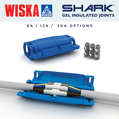
I use these wiska boxes to insulate small outdoor joints they can be put over any connectors.

Subscribers  do not see these advertisements

 
This site contains affiliate links for which MHF may be compensated.
I have a pre wired Chausson (flash 10) and have found the solar connection cables in a void at the end of the locker over the sink. However some have said that if the solar is connected there it only charges if you leave the panel on all the time and its better to run cables directly to the batteries. However we have had it 5 1/2 years now and still haven't got around to it we are often off grid but have little power use and drive every day so have never had a flat hab baterry and are still on the original!!
 
Thanks all. My original reason for asking the question is prompted by the fact that the easiest way to bring the panel cables down through the roof is inside the locker at the foot of the bed (French bed layout of MH) and then straight down inside this locker to the space below the foot of the bed. In here lies the charger and distribution box etc.

The leisure battery is also under the bed , easy access.

The vehicle battery of course is in the usual Fiat location, not easy at all.

However , a positive from the vehicle battery must be present under the foot of the bed connected to B1 in my diagramme. A test with a multimeter with the batteries at rest should confirm this. Of course this could be disconnected at rest by a relay etc.

Hench the thought of connecting the 2 outputs from the regulator.
 
I've just checked my CBE system and the voltage reading at +B1 is the same as at the vehicle battery (VB) voltage, at rest.

There is a 25amp fuse adjacent to the +VB post - the cable run with this fuse terminates at the +B1 stud.

Applying some logic, the electrical energy from the +VB post passes to the +B1 stud and onwards to the split charge relay on the CBE board and onwards to the +B2 stud (connected to the leisure battery). The only time the split charge relay disconnects is when the engine is cranking (drawing lots of amps from the VB).

When the engine is cranking, the cable from +VB to +B1 stud is effectively a "dead end" because the split charge relay is disconnected.

Based on this logic, l see no reason why the output from the solar regulator (vehicle battery) terminal cannot be connected to the +B1 stud with say a 5amp fuse.

Obviously, during alternator charging the small current from the solar regulator to the vehicle battery will be swamped by the larger current coming the other way to top-up the leisure battery.

Hope this all makes sense !!! Happy to be corrected if my logic is suspect :oops:
Wagoneer Sounds logical.
We shall see............

If I am correct I should be able to confirm this with the system at rest connecting the solar power should see a steady rise in voltage on both batteries. Although the regulator prioritises one battery first (to 70% or about 12.4v) , that will be the leisure battery in my case., then charges both.

Thank you for your help.
 

Join us or log in to post a reply.

To join in you must be a member of MotorhomeFun

Join MotorhomeFun

Join us, it quick and easy!

Log in

Already a member? Log in here.

Latest journal entries

Back
Top