Benivan tweaks and improvments (4 Viewers)

OP
OP
rwg

rwg

Sep 7, 2021
231
516
Funster No
84,021
MH
Benivan 120
Exp
Since 2021
Well today I have been making additional storage space in the van :)

AutoTrail (who build the Benivan) just box in the space fore and aft of the wheel arches - presumably because it's the simplest way to deal with it rather than try to do carpentry around complicated shapes. From my point of view, while we haven't run out of storage space, more would be good to avoid having to pack so carefully every time, and the van has a fair amount of payload (~600kg), so it's worth doing a bit of work to open up those spaces. I've seen a few posts on doing this on various sites (including Autotrail v-line ones, since the Benivan is pretty similar).

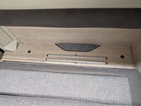
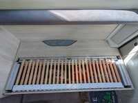
Here's a picture of the rear bench seats - cushions removed - showing that no access to the space fore and aft of the wheel arch...
PXL_20220907_110919065.jpg
The first thing to do is obviously to get the wooden panel behind the hinged seat base up. It's held in by about 9 screws on the top which are all under adhesive cover stickers. Using a hair dryer on hot lets you remove the stickers without any damage to the veneer of the panel (and put them on a plastic bag for re-use). Remove the screws from the top, and also remove the two covers and screws from the end adjacent to the rear doors.

The timber panel is now being held in by two screws at the front end (which you can't unscrew because either the oven or the fridge is in the way - depending on which side you are doing) and some staples at the back (both front and rear). Starting at the middle of the panel, get something underneath and prise gently upwards. I have a slim pry bar which does the trick. Work towards the rear of the van, lifting the front of the panel until you reach the part next to the rear doors. Keep prying - this should dislodge the staples at this end, so now you can lift the rear of the panel.
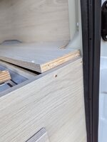
PXL_20221024_085332757.jpg
Lifting the rear 2 or so inches will start to pull on the screws that you cannot get at at the front end of the panel, hopefully making a gap of a millimetre or two. Once you have a bit of a gap, slip a fine tooth hacksaw blade into it (not junior hacksaw - those have bumps on the side - a full size hacksaw blade has smooth sides). You will find the two screws easily enough and within a few minutes be able to cut through them.
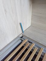
PXL_20221024_085351477.jpg
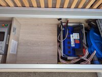
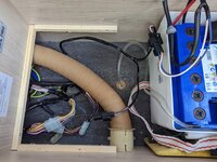
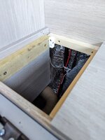
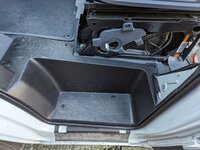
Once you have cut both screws, the only thing holding the board in will be the staples at the back of the board towards the front of the van - a little wriggling will work those free, revealing a good deal of space behind the wheel arch (more in a 6.36m van) and a bit of space in front of it...
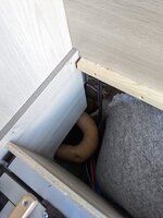
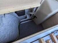
PXL_20221024_085924360.jpgPXL_20221024_085929596.MP.jpg

You might notice that there is limited (ie practically no) insulation below the seat level, but there is a heating duct down there. Nice design - something else to fix...

I've seen approaches using hinges along the front of the board so that the whole thing hinges up towards you, but wasn't really keen on that. Instead I decided to split the board into 3 - a central fixed section around the wheel arch and removable sections fore and aft to allow access to the new storage space. Obviously a little reinforcement is in order to make sure that the new, smaller, sections of board can support any required load. Off to the offcuts bin in the garage to find some bits and pieces of scrap wood and a few metal brackets...

PXL_20221024_124557636.jpg
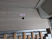
The old sliding compound mitre saw made short work of cutting the board into 3 (possibly the most useful DIY tool I've ever bought behind only a battery drill/driver). Pop a couple of 1 inch holes in the middle of the removable panels and you are nearly done - note that the screw cover stickers have been put back into place.
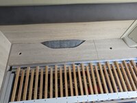
PXL_20221024_132205329.jpg
Actually, I also put some plastic blocks on the back of each removable section, carefully placed so that it sits snugly in the gap rather than rattling around.

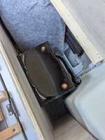
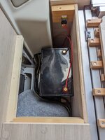
As a bonus, I discovered that the larger, rear space is perfect to take the new LiFePO4 leisure battery that I am about to fit.
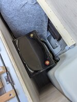
PXL_20221024_090312041.jpg
This will free up more space in the main under seat storage (where the current lead acid battery is). A bit of re-wiring required, but that will have to wait for another day. Anyway, I've got the same to do to the other side of the van first :)

cheers,

Robin
 
OP
OP
rwg

rwg

Sep 7, 2021
231
516
Funster No
84,021
MH
Benivan 120
Exp
Since 2021
Well, more progress to report :)

Firstly I opened up the storage space on the passenger side of the vehicle - this wasn't quite a carbon copy of the driver's side. For one thing whoever made the unit for the passenger side decided to use four screws at the front that all needed to be cut with a hacksaw blade :( . The other difference is that on the passenger side there are two recesses cut for the storage of the bed support rails.

PXL_20221030_211206743.jpg
These go all the way through the main ply board, with a backing board glued and stapled on from below. This meant a bit more reinforcement was required to ensure that the board once cut was still strong enough to take any loads placed on it. I put lengths of 2x1 running front to back (as seen in the picture above) at each end, and another running left to right under the cut out area. With some careful placement, the one running left to right can be arranged to actually sit on the wheel arch, providing direct support.

To tidy up, I 3D printed some inserts for the pull holes in grey plastic, which goes nicely with the van decor.

Next up, battery replacement with LiFePO4 leisure battery ... will do a separate post.

cheers,

Robin
 
OP
OP
rwg

rwg

Sep 7, 2021
231
516
Funster No
84,021
MH
Benivan 120
Exp
Since 2021
Right, this is a big one... Leisure battery upgrade to Lithium :)

PXL_20221026_135317070.jpg
Auto Trail put the leisure battery in the under-seat locker on the driver's side. It's a basic Banner 72Ah lead acid leisure battery in a plastic battery housing box. When the lid is on the battery box it uses most of the height of the locker, meaning that the storage space is effectively cut up by the battery in the middle. My original plan was to replace the battery with lithium in this location, but to do away with the storage box (or at least the domed lid) to make the locker space more usable. Once I found that the battery would fit into the newly opened space behind the wheel arch, I had a much better option available :)
PXL_20221024_090312041.jpg
As I've mentioned elsewhere, I bought a 105Ah Fogstar LiFePO4 battery for about £365 (using their 15% off on Friday discount code). The battery has a bluetooth enabled BMS and built in heating that should automatically come on to warm the battery if it needs to charge when below freezing. This should give nearly 3 times the usable capacity of the 72Ah lead acid battery that I'm replacing for about 1/2 the weight.

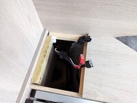
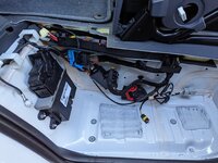
The first thing to do was to get access to the wiring of the leisure battery and see how everything was connected. Fortunately the shelf to to the left of the battery is only held in by two screws under sticky dot covers, and taking it out reveals a lot of the wiring, the heating duct and some sawdust left by the builders of the van :)

PXL_20221026_135437655.jpg
To be honest, I'd have thought that it wouldn't have been hard to reduce the width of that shelf by about 50% - it's not as though the space underneath is crammed with wiring and pipes...

Anyway, you can see that the leisure battery connects to a wiring harness coming from the ECU unit with push fit plugs (not quite sure whether compatible plugs are available easily - haven't found any in a quick search). There is even a second plug for a second battery. The ECU unit is just to the left of the view here.

There's a gap under the back panel just behind where the heating duct goes out of view - this is there to let through various cables from elsewhere in the van to reach the ECU. It's big enough to get the wiring harness through (plugs and all) once the existing leisure battery has been disconnected. Obviously other 12V power turned off first before doing this (disconnect solar panel, turn of mains charger).

If I could have found a compatible plug for the existing wiring harness, I could have just made my own new harness and plugged it in. No luck on sourcing the plug, so instead I cut the wires about 6 inches after the connection and used WAGO connectors (32A rated) to join to the new harness that I made.

PXL_20221027_082035055.jpg
This is 4mm2 cable (which is heavier weight than the existing wiring), and the battery fuse will remain at 20A, so the cable is fine for the job. The heatshrink on the wires to the fuse holder isn't the best - I don't have a heat gun and the 'shrink it with the side of the soldering iron' trick didn't work as well as it has in the past.

Here's the battery in place with the wiring attached and the battery fuse in place. The battery is secured by wooden blocks screwed to the floor to prevent it moving around while travelling.

PXL_20221029_161143580.jpg
I ordered some battery terminal covers, but selected the wrong size. New ones have been ordered, but seem to have got stuck in the postal strikes. When they arrive I will re-do the ring terminals with the terminal covers and new heatshrink.

At the other end of the bench, the new wiring harness connects to the old with the WAGO connectors.
PXL_20221029_161207426.jpg
The wiring will be secured tidily once I have the terminal covers in place - no point in cable-tying it all out of the way now and then finding it needs to be pulled out again in a few days time.

Just for finishing touches I peeled the 'Battery Compartment' sticker off the old battery box and popped it on the new locker lid :)

PXL_20221029_161248648.jpg

Everything seems to be working fine on the new battery so far, and it's nice to see the charge/discharge rate on the app. Interestingly the built in Sargent charger with it's simple 13.8V output managed to charge the battery up to full charge according to the app, although the charge rate was pretty slow above 90% full (3-4A). I switched the solar controller to a lithium profile that gives 14.4V bulk/absorbtion and 13.8V float, which is very close to the perfect setup according to the battery user manual.

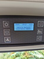
Previously I had a 12V bluetooth battery voltage monitor on the old leisure battery to keep an eye on it. No need for this on the new battery, so I moved it to the vehicle battery

PXL_20221027_110023217.jpg
Still a bit of tidying up and finishing touches to do on this upgrade, but the bulk of the job is done and very pleased with it too.

cheers,

Robin
Subscribers  do not see these advertisements

 
Oct 21, 2019
30
50
East Sussex
Funster No
65,906
MH
Benivan 120
Exp
since Feb 2018
Well done rwg. Some very interesting stuff! We get our 2021 benivan 120 next week so we will find out all the niggles soon enough! Apple car play will be one of the first things!
 
Oct 6, 2021
560
908
Funster No
84,698
MH
PVC
Well done rwg. Some very interesting stuff! We get our 2021 benivan 120 next week so we will find out all the niggles soon enough! Apple car play will be one of the first things!
Join the UK Benimar Owners Group on Facebook. Apple Car Play should work on the Xzent sat nav, though the sat nav itself is probably better for driving as it will try to avoid narrow roads and low bridges.
 
OP
OP
rwg

rwg

Sep 7, 2021
231
516
Funster No
84,021
MH
Benivan 120
Exp
Since 2021
Hi,

yes, the Benimar Owners Group is full of useful info. Another even better one for the Benivan is the 'Auto-Trail V-line owners Group' on Facebook. That's because the Benivan is built by Auto Trail and is a close relative of the V-line, built with the same parts and largely to the same design.

Sadly the XZent doesn't have real Android Auto or Apple Car Play (I expect because that would require them to pay a license fee for each one sold). Instead it has a custom app which can mirror the screen of the phone onto the XZent display. Unfortunately it doesn't work too reliably, and even when it does work, stuff appears on the display looking like it normally does on the phone, rather than the simple layout/easy-to-hit big buttons of Android Auto/Apple Car Play.

Birty - glad you enjoy the thread and hope that everything goes well with your new Benivan - we love ours despite a few teething problems.

cheers,

Robin
Subscribers  do not see these advertisements

 
OP
OP
rwg

rwg

Sep 7, 2021
231
516
Funster No
84,021
MH
Benivan 120
Exp
Since 2021
Well, I've been tinkering again :)

Having moved the battery into the behind-wheel-arch storage space, I started thinking that I could make more use of that space - turn it into an 'Electrics locker' of sorts. The plan eventually evolved to move the solar charge controller down to that space (clearing it out of the overhead locker and placing it nice and close to the battery). A future B2B charger can go there too. To keep everything wired in safely and tidily I decided to put in a small fuse box too and have everything connecting to the battery via the fuse box and appropriate fuses.

The first job was to run a cable down from the overhead locker to the new electrics locker to bring down the solar panel feed. Fortunately the soft backing panel behind the bench seat can be removed fairly easily on that side of the van, allowing a cable to be routed down out of the floor of the overhead locker, down the left side of the window frame, behind the wooden back panel of the bench seat and into the under-seat space. Don't worry, the condensation and damp is on the outside of the window!

PXL_20221128_092432787(1).jpg

All the other wiring would come from the main electrical unit under front end of the bench seat. In due course I would need

  • Leisure battery +12V and GND (Brown/Blue and White/Orange wires)
  • Vehicle battery +12V (Brown/Green wire)
  • D+ for a B2B (Orange/Yellow wire)

in addition to the solar panel input cables. I spent some time identifying the right cables at the wiring loom next to the main electrical unit (colours shown above) and running appropriate cables to the new battery locker. I used red/black twin 4mm2 (or maybe 4.5mm2) for the solar panel feed and the leisure battery connections, 2.5mm2 for the vehicle battery and 1mm2 for the D+ (which is just a signal). I know a lot of people would go with heavier duty cable, but the whole 12V system of the van is wired out in 2.5mm2 cable and fused at 20A, so I decided to just go along with that or upgrade slightly rather than going for overkill.

Next up was sourcing a suitable fuse box to help keep the wiring tidy and make sure that all the cables can be fused near any source of power to protect against shorts in the cable. I bought a 6 way 12V fusebox off of Amazon which takes blade fuses (Amazon product ASIN B09YTWFBT8). One key requirement was that all connections should be screw/bolt rather than push on spade terminals, which I feel are too prone to coming undone. The box is supposed to cope with a total of 100A and a max of 30A on each circuit, but when I popped the back off, I was a bit concerned by how little metal there was to carry the current to the blade fuse holders (seen here from the rear)

PXL_20221227_210515396.jpg

I decided to spend an hour or so with a soldering iron and some solid copper 2.5mm wire from household twin+earth cable to beef up the internals. As you can see, once done, every narrow bit is backed up by soldered on copper... Mind you, I did have to trim some of the support bits on the back panel of the fuse box to get it to go back on after upgrading...

PXL_20230102_121308146.jpg


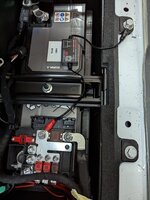
Here's the fuse box in place above the battery attached to a bit of 9mm ply cut to size.
PXL_20230108_142817176.jpg

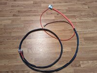
You can also see that I have gone for a decently chunky 16mm2 cable from the battery to the fusebox with an inline midi fuse (70A) within the first 6 inches of the +ve cable. The +ve cable up to the midi fuse is also double insulated with heatshrink for safety (even though the battery BMS should cut out at a 100A short anyway - better to have belt and braces...)

On the left in the image above you can see another piece of ply cut out to hold the solar controller and the B2B charger when I add that. This board is designed to lift out and slot back in for easy access to the wiring on these devices, as you can see in the photo below

PXL_20230109_142922725.jpg


Connections to the existing wiring are done with Wago connectors (how easy are those - must get more!). I have some further work to do, including putting a 10A screw in fuse in the Solar panel wiring into the top cupboard where the solar controller used to be - this will conveniently fill the hole left by the original solar charger leisure/vehicle switch, and provide a convenient way to disconnect the solar panel supply if necessary.

Further ahead, I intend to add a Victron IP65 charger in place of the Sargent 'dumb' 13.8V charger that comes with the van.

I am still thinking about how to do the B2B charger - working from the existing wiring that used to allow the split charge circuit to 'work', I could fit a 20A B2B with no need to run new wiring (Votronic 12-12-20C keeps the input current below 20A), or I could run heavier cabling back from the vehicle battery and fit a bigger B2B. Since we seem to use the van largely on EHU sites, the B2B is only a fallback, so a smaller one is probably OK.

Anyway, good progress so far - when I'm done the 12V electrical system on the van will be vastly improved from how it started out, and it will be largely tucked away, freeing up locker space rather than using it up :)

cheers,

Robin
 
OP
OP
rwg

rwg

Sep 7, 2021
231
516
Funster No
84,021
MH
Benivan 120
Exp
Since 2021
Well, I spent some of the day digging around in the van looking for ways to potentially run a cable from the vehicle battery back to a B2B charger at the rear of the van.

Starting at the back of the van where I have the battery now, it's easy to get to the front end of the driver's side bench seat behind the locker. From there, there are gaps behind the fridge and bathroom (just above seat level) that lead through to the toilet cassette door.

PXL_20230113_120247511.jpg

From the toilet cassette you can then find your way through to the base of the pillar by the driver's seat - the black surround at the base of the pillar comes off with a few screws and a single clip catch.

PXL_20230113_104715682.jpg
It's then possible to run across the van under the raised floor section to the equivalent point on the passenger side, bringing you to just behind the passenger seat.
PXL_20230113_115516377.jpg
I just have to work out the best route from this point behind the passenger door into the vehicle battery compartmet - I think the plastic trim round the base of the passenger door recess needs to come out, but a job for another day.

A coil of nylon fish tape let me thread string through all of these gaps, which will make it easier to run the cable if I intend to go down that route.

cheers,

Robin
 
Jan 1, 2017
1,161
2,618
eastbourne
Funster No
46,681
MH
van conversion, Peug
Exp
4 years
Well, I've been tinkering again :)

Having moved the battery into the behind-wheel-arch storage space, I started thinking that I could make more use of that space - turn it into an 'Electrics locker' of sorts. The plan eventually evolved to move the solar charge controller down to that space (clearing it out of the overhead locker and placing it nice and close to the battery). A future B2B charger can go there too. To keep everything wired in safely and tidily I decided to put in a small fuse box too and have everything connecting to the battery via the fuse box and appropriate fuses.

The first job was to run a cable down from the overhead locker to the new electrics locker to bring down the solar panel feed. Fortunately the soft backing panel behind the bench seat can be removed fairly easily on that side of the van, allowing a cable to be routed down out of the floor of the overhead locker, down the left side of the window frame, behind the wooden back panel of the bench seat and into the under-seat space. Don't worry, the condensation and damp is on the outside of the window!

View attachment 704632
All the other wiring would come from the main electrical unit under front end of the bench seat. In due course I would need

  • Leisure battery +12V and GND (Brown/Blue and White/Orange wires)
  • Vehicle battery +12V (Brown/Green wire)
  • D+ for a B2B (Orange/Yellow wire)

in addition to the solar panel input cables. I spent some time identifying the right cables at the wiring loom next to the main electrical unit (colours shown above) and running appropriate cables to the new battery locker. I used red/black twin 4mm2 (or maybe 4.5mm2) for the solar panel feed and the leisure battery connections, 2.5mm2 for the vehicle battery and 1mm2 for the D+ (which is just a signal). I know a lot of people would go with heavier duty cable, but the whole 12V system of the van is wired out in 2.5mm2 cable and fused at 20A, so I decided to just go along with that or upgrade slightly rather than going for overkill.

Next up was sourcing a suitable fuse box to help keep the wiring tidy and make sure that all the cables can be fused near any source of power to protect against shorts in the cable. I bought a 6 way 12V fusebox off of Amazon which takes blade fuses (Amazon product ASIN B09YTWFBT8). One key requirement was that all connections should be screw/bolt rather than push on spade terminals, which I feel are too prone to coming undone. The box is supposed to cope with a total of 100A and a max of 30A on each circuit, but when I popped the back off, I was a bit concerned by how little metal there was to carry the current to the blade fuse holders (seen here from the rear)

View attachment 704635
I decided to spend an hour or so with a soldering iron and some solid copper 2.5mm wire from household twin+earth cable to beef up the internals. As you can see, once done, every narrow bit is backed up by soldered on copper... Mind you, I did have to trim some of the support bits on the back panel of the fuse box to get it to go back on after upgrading...

View attachment 704636

Here's the fuse box in place above the battery attached to a bit of 9mm ply cut to size.
View attachment 704639
You can also see that I have gone for a decently chunky 16mm2 cable from the battery to the fusebox with an inline midi fuse (70A) within the first 6 inches of the +ve cable. The +ve cable up to the midi fuse is also double insulated with heatshrink for safety (even though the battery BMS should cut out at a 100A short anyway - better to have belt and braces...)

On the left in the image above you can see another piece of ply cut out to hold the solar controller and the B2B charger when I add that. This board is designed to lift out and slot back in for easy access to the wiring on these devices, as you can see in the photo below

View attachment 704641

Connections to the existing wiring are done with Wago connectors (how easy are those - must get more!). I have some further work to do, including putting a 10A screw in fuse in the Solar panel wiring into the top cupboard where the solar controller used to be - this will conveniently fill the hole left by the original solar charger leisure/vehicle switch, and provide a convenient way to disconnect the solar panel supply if necessary.

Further ahead, I intend to add a Victron IP65 charger in place of the Sargent 'dumb' 13.8V charger that comes with the van.

I am still thinking about how to do the B2B charger - working from the existing wiring that used to allow the split charge circuit to 'work', I could fit a 20A B2B with no need to run new wiring (Votronic 12-12-20C keeps the input current below 20A), or I could run heavier cabling back from the vehicle battery and fit a bigger B2B. Since we seem to use the van largely on EHU sites, the B2B is only a fallback, so a smaller one is probably OK.

Anyway, good progress so far - when I'm done the 12V electrical system on the van will be vastly improved from how it started out, and it will be largely tucked away, freeing up locker space rather than using it up :)

cheers,

Robin
Amazing stuff

Subscribers  do not see these advertisements

 
  • Like
Reactions: rwg
Oct 6, 2021
560
908
Funster No
84,698
MH
PVC
Much of this seems complete overkill. The original battery has a 20 amp in line fuse, which is more than plenty. Indeed charging a lead acid battery at anything more than this will damage it. Therefore putting 4 mm cable which will take near enough 40 amps is pointless, and fitting a 70amp fuse is completely useless. The fuse is there to protect the cable. Voltage drop is not a real issue, the distances are small and the currents low. 2.5mm cable is more than enough and will easily handle 25 amps. The solar panel will only output 8amps on a very bright day in summer, and normally far less than that. 8 amps will give a voltage drop of 6mv per metre using 2.5mm cable, which as I said above is insignificant. Less current, and the voltage drop is even smaller.

Not sure why you'd want to got to all the trouble of wiring a B2B directly to the battery. I fitted a small B2B in place of the solar panel charging switch. Cost £40 and took less than 20 minutes to fit, with no additional wiring. Basically the purpose of a B2B is to keep the vehicle battery fully charged. The only time this is really an issue is over the winter period, and if, like mine, it is in storage its useful to be able to keep both batteries topped up at once. There is no big drain on the vehicle battery even with a tracker fitted.

The 100w solar panel puts out 0.5 amp in the middle of the day in winter. My B2B will supply up to 3 amps from the leisure battery to top up the vehicle battery. I took my Benivan out of storage last week where it had been for the last two and a half months. With this arrangement, both batteries remained fully charged.
 
OP
OP
rwg

rwg

Sep 7, 2021
231
516
Funster No
84,021
MH
Benivan 120
Exp
Since 2021
Ah, well, the reason I have used a lot of 4-4.5mm cable is that I ended up with a large quantity of it in 'twin red+black' form for free, so best to use it.

I am intending to continue the upgrade of the electrics, so in the future I may have a higher capacity mains charger (to refill the battery faster - the Lithium battery will take up to 50A), etc. Given that, the cost of a meter each of 16mm cable is not worth worrying about - a 70A fuse protects that, and its future proof.

You have the B2B thing the other way round compared to the one I am considering... I am looking at a charger that will charge the leisure battery while driving (alternator power to leisure battery) as opposed to a vehicle battery maintainer that you are describing. Once upon a time you had a split charge relay for this sort of thing, but that doesn't work properly with a vehicle with a smart alternator or start/stop since the relay will allow power to flow both into and out of the leisure battery. When the vehicle decides to drop the alternator voltage when you are accelerating, the relay will allow the leisure battery to discharge to support the vehicle electrics.

Sadly lots of vans are still being built with a split charge relay, even if they have start/stop or smart alternators - the manufacturers of van electrical systems like Sargent haven't caught up with the change to vehicle electrics, at least not at the bottom end of the range. I tracked this with a bluetooth battery voltage monitor on the leisure battery while driving and it was very clear that the voltage would drop during periods of acceleration. For now, I have blocked the Sargent split charge system by replacing the 'Vehicle Battery' fuse in the PSU with a deliberately blown one with a 1K resistor soldered across the pins (the resistor means the Vehicle battery voltage still shows on the display).

Anyway, my goal with the B2B is to bring back the capability to charge while driving that I have had to disable due to the silly split charge/smart alternator setup on the 2021 Benivan. Of course if your model is non stop/start then you don't have to worry about this.

cheers,

Robin
 
OP
OP
rwg

rwg

Sep 7, 2021
231
516
Funster No
84,021
MH
Benivan 120
Exp
Since 2021
and fitting a 70amp fuse is completely useless. The fuse is there to protect the cable.
Ah, I realize now that maybe you missed the fact that the 70 amp fuse is protecting a 16mm^2 cable which runs from the battery +ve to the fusebox. The individual circuits from the fusebox are protected by appropriate size fuses (20A to the main PSU box, etc).

cheers,

Robin
Subscribers  do not see these advertisements

 
OP
OP
rwg

rwg

Sep 7, 2021
231
516
Funster No
84,021
MH
Benivan 120
Exp
Since 2021
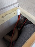
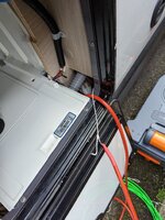
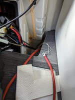
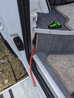
Well, in the last few days I have been working on the B2B installation again. The first steps were to run the 16mm^2 positive cable through the route I had planned from the rear of the van to the vehicle battery. Since I already had string through each section, this wasn't too difficult - the trickiest part was threading it under the floor of the toilet cassette locker.

PXL_20230120_110149423.jpgPXL_20230120_110116371.jpgPXL_20230120_112049870.jpgPXL_20230120_112144822.jpg

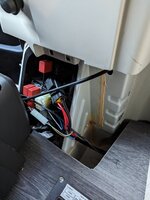
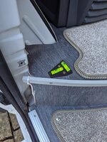
That gets you to just behind the passenger seat, so the last stage is to get from there to the verhicle battery compartment. To do this, remove the left hand panel from the base of the passenger seat, which then allows you to remove the plastic footwell of the passenger door (once you have removed another small piece of trim from the side of the passenger door next to the glove box.

That gets you from this...

PXL_20230120_112741530.jpg

to this...

PXL_20230120_113132766.jpg

Lots of interesting electronic boxes down there, but the important thing is that there is plenty of space to route the cable under the floor and then run it through into the battery compartment - you can see it just pushed over out of the way in this final photo.

PXL_20230120_114325737.jpg


Refitting is the opposite of removal as they say, so with the cable in place, time to put back all the trim round the passenger door and behind the passenger and driver's seats.

As the van is a PVC with a metal shell, allowing the return current to flow through the chassis/body should be fine, but I was unsure of what earthing to the body was already in place (and where, and what current capacity), so I decided to add a separate earthing to the body next to the leisure battery. Fortunately there is a nice bolt hole on the wheel arch in pretty much the right place, although sanding off enough paint to ensure a good electrical contact was a fiddly procedure...

I had ordered a 150A bus bar to make wiring in the negative connections tidier - it turned out to be rather bigger than I had expected, but I still just had space to fit it into the battery compartment

PXL_20230125_131528632.jpg

You can see my connection to the bodywork on the left, which connects to the busbar. The other connections are to the -ve of the leisure battery, the fusebox as shown about 6 or 8 posts up and the final one will be the -ve to the B2B charger.

The final bit of preparation was to tap into the D+ wire at the existing Sargent controller so that can switch the B2B. I had previously identified the D+ as being the orange and yellow wire, so I cut into that and spliced in my own cable to the B2B using a wago connector.

PXL_20230125_140934988.jpg

You can see that I have also patched into the vehicle battery cable here (for the dual solar controller) and the original leisure battery connections. I've become a bit obsessive about labelling new wires unless it is entirely obvious about what they are for - it only takes a minute or two, and might be useful later (particularly if you get someone else to work on your van).

Anyway, enough for this post - I have all the other bits of cable made up to connect in the B2B and am hoping to get it all working tomorrow.

cheers,

Robin
 
OP
OP
rwg

rwg

Sep 7, 2021
231
516
Funster No
84,021
MH
Benivan 120
Exp
Since 2021
Today was finish the B2B day, and fortunately everything went off without a hitch :)

The first thing I did (before connecting the B2B to either battery) was start the engine and check I got 12V at my D+ connection. That was fine, so I connected the vehicle and leisure batteries up via the appropriate fuses (50A for vehicle battery, 40A for leisure). I think I should have made a shorter section of cable to go between the vehicle battery and the fuse, but I am out of heatshrink for now, so I will replace that later.

PXL_20230126_092512178.jpg
PXL_20230126_093742545.jpg


Next, a test of the system with everything wired up - start the engine, check that the charging light turns on on the B2B (it does) and check the battery app

Screenshot_20230126-092135.png


Hooray! Charging at 31.3A - close enough to the 30A expected. All that was left now was to tidy everything up, and make sure the wiring was as neat as possible.

PXL_20230126_102428441.jpg

The addition of a few cable ties, a bit more cable sleeving and some labels helps. The cables are still deliberately left longer than normal (by about 50cm or so) so that the board with the B2B and MPPT on can be lifted out (and so, in theory can the battery, without having to disconnect anything).

Here's what it looks like with the board back in place

PXL_20230126_102731934.jpg


All of the electrics tucked away without using any of the original locker space :)

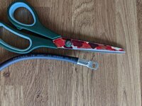
I have learnt a few things along the way... One is that surprisingly the best thing to cut through the copper part of heavy duty cables is a pair of domestic scissors - they do a far better job than wire cutters, side cutters, etc. The other is that not all copper tube ring connections are the same - the second batch I bought were significantly heavier duty than the first, and my crimping tool wouldn't touch them. Fortunately a good tweak in a vice clamps them shut nicely!

PXL_20230125_112935313.jpg

I'm still undecided about replacing the existing Sargent mains charger - it works, but doesn't charge very fast due to the 13.8V output - only 6A at 80% battery charge, dropping further as the battery fills. I think I will leave this for now and see if the slow charge rate is ever a problem.

cheers,

Robin
 
OP
OP
rwg

rwg

Sep 7, 2021
231
516
Funster No
84,021
MH
Benivan 120
Exp
Since 2021
Been a bit quiet on the tinkering front recently, but today I had a quiet morning and all the bits I needed to replace the shower tap.

Replace the shower tap you say? Why would you do that in a nearly new van? Well, I say why would you put the shower tap here?

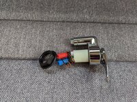
PXL_20230302_094023450.jpg

Yep, unless you sit very carefully, it jabs you in the side or the back.

To be fair, I know why they put it there - it's easy to install... You can reach through the cut out for the toilet flush panel and fix it from there. Not so easy for the people who have to live with it though...

So, based on some suggestions on the AutoTrail V-line owners group, I'd sourced a replacement low profile shower tap - one of these : https://magnummotorhomes.co.uk/shop...er-keramik-twist-shower-mixer-f243s-mag00060/ - and the necessary 12mm plumbing bits and bobs to plumb it in.

Access to the back is either up from the toilet cassette hatch, or (much easier) by removing the toilet flush panel, which is just clipped into the wall. Once you can reach round behind the tap, you can undo the back nut and remove that and the horseshoe washer (just like those for a monobloc kitchen tap) and bring the tap out of the wall, still attached to its flexible tails. It's a 10mm spanner for the back nut, in case you need to know ;)

PXL_20230302_094747320.MP.jpg


Next, down to the toilet cassette hatch and disconnect the tap tails there (having drained the water out of the van first, obviously!)

PXL_20230302_095145625.jpg


Two push fit splitters for the hot and cold pipes - the supply coming from somewhere further forward and two sets of tails going to the bathroom sink and the shower. Turned out the top one of each pair goes to the shower, so out they came, allowing the tap to be fully removed.

PXL_20230302_095358778.jpg


Of course, the hole left by the old tap was a bit too small for the new one to go through - isn't it always - but 5 minutes with a half round wood rasp fixed that problem...

PXL_20230302_095553302.jpgPXL_20230302_095450130.jpgPXL_20230302_100727346.jpg

With the new tap in place, it was time to start on reconnecting the plumbing, so I made up two lengths of pipe a little longer than the tails on the old tap with a push fit elbow on each end.

PXL_20230302_101902779.jpg

The unconnected end of the elbow will push onto the back of the tap (the two connectors there are plain 12mm, designed for push fit), and the other end will, with trimming if necessary, connect to the existing plumbing. For reliability, using hose inserts in each end of the hose and locking clips.

It was a bit fiddly reaching round the back to push the elbows onto the back of the tap, and even more fiddly trying to put the little locking clips onto the push fit once they were installed, but the worst that happened was that I lost one of the locking clips into the depths of the van - still I had spares...

With everyting connected up at the tap end, time to connect to the plumbing. Not too hard, since it's just push fit

PXL_20230302_111758799.jpg

All it needed from there was a new cable tie to hold them back up in place.

A quick refill of the water system and leak check later (all good), and everything can go back in place inside

PXL_20230302_113405621.jpg

It still needs a new bead of silicone around the toilet flush plate, but now a chap (or chapess) can sit down in comfort.

cheers,

Robin
Subscribers  do not see these advertisements

 
Oct 21, 2019
30
50
East Sussex
Funster No
65,906
MH
Benivan 120
Exp
since Feb 2018
I had two Xzent A-F270’s fail. Everything on them was flakey and only worked when it wanted to. Sat Nav froze on a fairly regular basis. Niether Unit had Android Auto, updating was a nightmare.

The Specialist company removed the Fiat USB socket (seen in the picture above) and replaced it with a double USB fitted in the hole it left. Both USB’s show on the Pioneer Unit and work easily in conjunction with updates. They changed the rocker switch ( giving power when the ignition is off) for one that they put in all the vehicles they work on. The Motorhome Dealer couldn’t get 3 of 5 (1 x Zenec, 1 x Alpine and 1 x Pioneer) replacement units to work with the steering wheel controls……they needed to fit a ‘Patch’ kit for that to happen🤦‍♂️). That’s why I gave up and found a company that knew what they were doing.
View attachment 675854

Following your thread with interest. (y)
Just curious as to which company/area you used to install it? Have you been happy with it and is it apple CarPlay?
 

Sapper520

Free Member
Jan 22, 2020
2,879
4,506
North Somerset
Funster No
68,245
MH
No longer own one
Exp
September 2020
I was very happy with it…..but the van’s been sold now.

Fitted by a company in Bristol.
 
Oct 21, 2019
30
50
East Sussex
Funster No
65,906
MH
Benivan 120
Exp
since Feb 2018
Part of the fun (for me anyway) of a motorhome comes from having something to tinker with and improve. Something to do with your van when you can't actually get away in it :) So... I thought I would post a thread on the tweaks and improvements that I have made to our Benivan 120. Maybe the information will be useful to other Benivan owners (or to Auto Trail PVC owners for that matter, as in spite of the Benimar name, the Benivan is made by Auto Trail and has a lot in common with their vans).

I'll start with a couple of simple bathroom tweaks...

First, a 3D printed box to hold the hand soap bottle on the sink top. A few strips of double sided tape on the underside to hold the box in place and the soap bottle is not going to slide around anwhere when you are on the road. Another hint - drill a small hole in the neck of the soap bottle just below the lid (2mm or so). This lets air into and out of the bottle. Without this we found the soap was pumping itself out due to the temperature changes over the winter.

View attachment 623840

As you can see from the image above, the Benivan has a tip up sink unit in the bathroom - the idea is that the water drains out when you tip it up (no plug hole in the sink). This is fine in theory, but if you are a bit swift tipping the sink up then the water doesn't go into the drain down the back, but instead dribbles out down the front of the lower part of the unit and onto the shelves below :(

View attachment 623841

Fortunately there is a thing called 'Silicone seal strip' - clear/translucent silicone tape that has self adhesive tape on about half its width. It's designed for sticking to places like the bottom of doors, so that the non-adhesive part reaches to the floor and cuts out a draught, but I've stuck it to the lower part of the sink unit to help catch any dribbles and guide them in the right direction.

View attachment 623845View attachment 623846

It's fairly subtle against the white of the bathroom unit and seems to be doing the job OK.

Next time... strengthening the wardrobe wall to mount a TV.

cheers,

Robin
Hi Robin . Done many of your 'mods' now thanks! New solar unit, bungees on shelves, created space under seat and moved the battery into it! But could you just clarify which Silicone seal strip you used, if you can remember, and has it been a success? Thats probably my next job along with a new leisure battery or otherwise! Would love to go fully off grid electrically and been looking at systems by Clayton power but pricey!
Like those - very handy mods that may help others (y) Look forward to seeing more in case we can use any of them too as do like a mod. https://www.motorhomefun.co.uk/foru...vc-modding-accessories-discount-codes.184590/

Like those - very handy mods that may help others (y) Look forward to seeing more in case we can use any of them too as do like a mod. https://www.motorhomefun.co.uk/foru...vc-modding-accessories-discount-codes.184590/

Subscribers  do not see these advertisements

 
OP
OP
rwg

rwg

Sep 7, 2021
231
516
Funster No
84,021
MH
Benivan 120
Exp
Since 2021
Hi Birty,

good to hear that the mods have been going well :)

This is the Amazon listing that I bought from, BUT I bought a 25mm width version that seems to be no-longer on the listing : Amazon product ASIN B081J569Z6
I don't suppose a slightly wider version would hurt - you could just place it a little further down the slope to avoid too much sticking forwards (you need a centimeter or so to catch the drips).

So far, I'm not convinced we need mains power when off-grid... I think the only electrical thing we have in the van that needs 240V is the electric kettle. Maybe in time there will be a good reason, but until that becomes apparent, I'm happy to stick with 12V power ;)

cheers,

Robin
 
OP
OP
rwg

rwg

Sep 7, 2021
231
516
Funster No
84,021
MH
Benivan 120
Exp
Since 2021
Here's another little tweak that I've just finished up...

You might already know that the UK Benivan is made by AutoTrail and shares a lot of parts with the AutoTrail 'V-Line' range of PVCs. One of those parts is the Sargent made electrical system and EC362 control panel.

PXL_20220915_142330967.jpg
From posts on one of the AutoTrail V-Line facebook groups, it was clear that the same control panel was showing temperature readings on the V-Line, but no temperature reading on the Benivan. Since I'd already found the option in the advanced settings of the control panel to turn temperature sensors on or off, I thought it might be worth seeing if I could actually add temperature sensors to the Benivan...

Taking the control panel off the wall is easy enough - the surround just pops off and then there are two screws to undo. Flip the panel over to reveal the back and there are indeed connectors for internal and external temperature sensors.

PXL_20230728_110447143~2.jpg

The other connectors are the blue cable (data connection to the main PSU), power in on the left and water level sensors on the top left. It's interesting that there are two connectors marked 'CAN' - the only reference I can find to these suggests that one can connect to a tracker system when manufacturer fitted. I do wonder if the other might be used to connect a 'remote control' unit to support the 'My AutoTrail' app on newer vans...

Anyway, my target is the two pin 'Ext Temp' sensor connection. With just two pins it's almost certain to be a thermistor, but there are lots of possible ones. However, Sargent themselves sell an external temperature probe listed for the EC328 unit - https://sargentltd.co.uk/shop/product/ec328_external_temperature_probe/146 - so I decided to order one and see what I got...

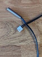
PXL_20230802_124858374.jpg
Well, the answer was a stainless steel temperature probe, about 3m of cable and a 2 pin connector. The thermistor measured about 10.6K at 23C and 23K at 4.5C in the fridge.

Unfortunately the 2 pin connector wasn't the right size to fit onto the control panel - the pin spacing was correct, but the holes in the connector on the probe cable were smaller than the pins on the board. Fortunately a cable with the right connector was easy to get (https://www.ebay.co.uk/itm/22353203...d=link&campid=5338547443&toolid=20001&mkevt=1) and it wasn't hard to splice the two together.

That let me test out my sensor on the control panel - enable the temperature sensors in the advanced settings then plug in, power on and ...

PXL_20230802_130902489.jpg

Yep, a temperature reading, and even a fairly much correct one!

That, of course, leaves the hard part of pretty much any motorhome project to do... Routing the cables :)

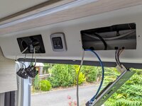
The control panel is above the sliding door and the sensor needs to go under the van to be out of the sun (otherwise the readings will be rubbish). A helpful person on the VLine facebook group told me that his built in temperature sensor wire was routed out through one of the gas drop vents in the lower cupboards, which I decided to copy.

So... along behind the trim above the door, behind the flyscreen, round the rear edge of the door opening tucked into the rubber door seal strip, behind the kitchen cupboards. Into the middle cupboard via the existing wiring hole in the back and through the gas drop vent under the van. I ran a separate, heavier duty cable for most of the run and then connected it to the sensor at one end and the panel connector at the other. The cable on the sensor might have just reached, but it would have been close.

PXL_20230804_145856817.MP.jpgPXL_20230804_144100443.jpgPXL_20230806_151553579.jpgPXL_20230806_151327024.jpgPXL_20230806_154426666.jpg
Under the van, it's cable tied to one of the gas pipes, high enough up to be safe from being knocked and well away from the main spray areas from the front wheels.

With everything back in place, it works nicely and seems to give a relatively accurate temperature readout. The external temperature reading is at the top right which previously showed the control panel version info.

PXL_20230806_154326599.jpg

The one issue is that turning on the 'temperature sensors' option also enables an internal temperature and humidity readout page on the control panel, and since I haven't got an internal sensor, both of those read zero.

So... if anyone has one of these and does have the internal temperature sensor, I'd be very grateful for photos of the sensor itself (any part numbers etc) and the wiring at the sensor end and the control panel plug. It's entirely possible that the internal sensor could be a commodity component like the DHT11 (Amazon product ASIN B07TXR5NQ6)...

cheers,

Robin
 
OP
OP
rwg

rwg

Sep 7, 2021
231
516
Funster No
84,021
MH
Benivan 120
Exp
Since 2021
I forgot to mention that I was heavily supervised while wiring this in...

PXL_20230806_144050253.jpg

Apparently it doesn't get much better than sitting on a hot dashboard in the sun while your human gets on with working :)

Robin

Subscribers  do not see these advertisements

 
OP
OP
rwg

rwg

Sep 7, 2021
231
516
Funster No
84,021
MH
Benivan 120
Exp
Since 2021
Another little job finished off...

We had a slow puncture a while back, and after one go of pumping up the tyre again with a foot pump I bought a heavy duty compressor (Ring RAC900). Unfortunately this takes more than 10A to run, so cannot be run from a standard 12V socket. It comes with crocodile clips to attach to the battery terminals, but that's rather crude, so I decided to wire in a high current socket for when I next need to use it.

I bought some 50A Anderson connectors off of ebay (not forgetting to get the pins too). Cut the cable from the compressor a couple of feet from the crocodile clips and put an Anderson connector on each cut end. Next, I ran a cable from my 12V fusebox and put another Anderson connector on the end. Rather than buy a mounting plate for the connector, I 3d printed one (this one, to be precise : https://www.thingiverse.com/thing:3883142)

All that was left to finish off was cutting a hole in the end of the bench seat behind the barn doors for the connector to fit through. In the end it came out quite well I think

PXL_20230815_090923454.jpg

Any time I need to pump the tyres I can just plug the compressor into that and off I go. I suppose in theory I could connect something else that takes relatively high power or even an external solar panel + controller that way.

cheers,

Robin
 
Jul 20, 2023
41
85
Battle, East Sussex, UK
Funster No
97,489
MH
Devon Aztec XL Auto
Exp
Limited motorhome and campervan hire previously.
Another little job finished off...

We had a slow puncture a while back, and after one go of pumping up the tyre again with a foot pump I bought a heavy duty compressor (Ring RAC900). Unfortunately this takes more than 10A to run, so cannot be run from a standard 12V socket. It comes with crocodile clips to attach to the battery terminals, but that's rather crude, so I decided to wire in a high current socket for when I next need to use it.

I bought some 50A Anderson connectors off of ebay (not forgetting to get the pins too). Cut the cable from the compressor a couple of feet from the crocodile clips and put an Anderson connector on each cut end. Next, I ran a cable from my 12V fusebox and put another Anderson connector on the end. Rather than buy a mounting plate for the connector, I 3d printed one (this one, to be precise : https://www.thingiverse.com/thing:3883142)

All that was left to finish off was cutting a hole in the end of the bench seat behind the barn doors for the connector to fit through. In the end it came out quite well I think

View attachment 796983
Any time I need to pump the tyres I can just plug the compressor into that and off I go. I suppose in theory I could connect something else that takes relatively high power or even an external solar panel + controller that way.

cheers,

Robin
Hi, Robin.
Thanks for all the detailed install info. Very much the things I would do. I am currently tempted by a 2023 Benivan 122 with 500 miles Auto and 180bhp (demonstrator). Do you still feel the Benivan is a good choice?
John
 
OP
OP
rwg

rwg

Sep 7, 2021
231
516
Funster No
84,021
MH
Benivan 120
Exp
Since 2021
Hi John,

we went to the NEC show last week - not really looking for a new van, but interested to see if we spotted anything that would suit us better than the current one. We didn't find anything at all... Of course, it all depends on the layout you want. We like the rear lounge converting to a transverse bed and the fact that you have a second space in the front of the van (a small table point and rotating chairs in the 120, dinette in the 122).

The things that we didn't like in terms of layout were

  • Rear washrooms, kitchens or full height storage in panel vans - a waste of the opening doors
  • Rear fixed beds for the same reason. U shaped lounges too, but at least you can open the door and look out
  • Full height furniture on both sides of the van at the same point - ie wardrobe opposite bathroom, etc - it makes it feel constricted.
  • Sliding door on the wrong side for the UK

That ruled out an awful lot of the vans at the show!

I think there was an AutoTrail v-line that would have been fine, but then the current Benivan is basically a v-line with slightly different options ticked. Note that the new Benivan that is coming in is cheaper, a bit more down market, sliding door on the wrong side for the UK and I suspect being made in Spain by Benimar - it's not the same at all.

So, if the layout suits you then it's a decent van. The build quality isn't top end and you will end up tweaking/fixing/improving things as you go. If you're happy with that then hopefully you will enjoy the van. The 9 speed auto gearbox is really relaxing to drive. I wish ours had adaptive cruise control rather than just basic, but maybe the newer 2023 version has that.

Just on the subject of the Fiat base vehicle, the one you are looking at will almost certainly be the newer Ducato8 - there have been some issues on here I've seen with the oil level sensor freaking out (no dipstick!) and also with weirdness regarding the trip computer - not sure if they have been fixed yet.

cheers,

Robin

Subscribers  do not see these advertisements

 
Oct 6, 2021
560
908
Funster No
84,698
MH
PVC
Hi, Robin.
Thanks for all the detailed install info. Very much the things I would do. I am currently tempted by a 2023 Benivan 122 with 500 miles Auto and 180bhp (demonstrator). Do you still feel the Benivan is a good choice?
John
I like my Benivan, but I suggest you look at the 2024 new models and prices first. The price has dropped by £20k for the Benivan 144, although some standard items on the 2023 model are now extras. They will be made in Spain in future rather than in the Auto Trail factory, but it appears the AT have dropped in price similarly.
 
Jul 20, 2023
41
85
Battle, East Sussex, UK
Funster No
97,489
MH
Devon Aztec XL Auto
Exp
Limited motorhome and campervan hire previously.
I like my Benivan, but I suggest you look at the 2024 new models and prices first. The price has dropped by £20k for the Benivan 144, although some standard items on the 2023 model are now extras. They will be made in Spain in future rather than in the Auto Trail factory, but it appears the AT have dropped in price similarly.
All change please... thanks for the info. Wednesday I had the opportunity to buy a Devon Aztec XL 140 automatic on a 21 plate. Drove 6 hours to look at it and paid a deposit minutes before another viewer turned up. Let battle commence next week when I travel back up to Durham to collect it..
So Benivan not on the radar anymore.
 
Jun 10, 2016
50
24
Cambridge UK
Funster No
43,531
MH
Autotrail
Exp
2016
Here's another little tweak that I've just finished up...

You might already know that the UK Benivan is made by AutoTrail and shares a lot of parts with the AutoTrail 'V-Line' range of PVCs. One of those parts is the Sargent made electrical system and EC362 control panel.

View attachment 791976
From posts on one of the AutoTrail V-Line facebook groups, it was clear that the same control panel was showing temperature readings on the V-Line, but no temperature reading on the Benivan. Since I'd already found the option in the advanced settings of the control panel to turn temperature sensors on or off, I thought it might be worth seeing if I could actually add temperature sensors to the Benivan...

Taking the control panel off the wall is easy enough - the surround just pops off and then there are two screws to undo. Flip the panel over to reveal the back and there are indeed connectors for internal and external temperature sensors.

View attachment 792024
The other connectors are the blue cable (data connection to the main PSU), power in on the left and water level sensors on the top left. It's interesting that there are two connectors marked 'CAN' - the only reference I can find to these suggests that one can connect to a tracker system when manufacturer fitted. I do wonder if the other might be used to connect a 'remote control' unit to support the 'My AutoTrail' app on newer vans...

Anyway, my target is the two pin 'Ext Temp' sensor connection. With just two pins it's almost certain to be a thermistor, but there are lots of possible ones. However, Sargent themselves sell an external temperature probe listed for the EC328 unit - https://sargentltd.co.uk/shop/product/ec328_external_temperature_probe/146 - so I decided to order one and see what I got...

View attachment 791993
Well, the answer was a stainless steel temperature probe, about 3m of cable and a 2 pin connector. The thermistor measured about 10.6K at 23C and 23K at 4.5C in the fridge.

Unfortunately the 2 pin connector wasn't the right size to fit onto the control panel - the pin spacing was correct, but the holes in the connector on the probe cable were smaller than the pins on the board. Fortunately a cable with the right connector was easy to get (https://www.ebay.co.uk/itm/22353203...d=link&campid=5339023013&toolid=20001&mkevt=1) and it wasn't hard to splice the two together.

That let me test out my sensor on the control panel - enable the temperature sensors in the advanced settings then plug in, power on and ...

View attachment 792006
Yep, a temperature reading, and even a fairly much correct one!

That, of course, leaves the hard part of pretty much any motorhome project to do... Routing the cables :)

The control panel is above the sliding door and the sensor needs to go under the van to be out of the sun (otherwise the readings will be rubbish). A helpful person on the VLine facebook group told me that his built in temperature sensor wire was routed out through one of the gas drop vents in the lower cupboards, which I decided to copy.

So... along behind the trim above the door, behind the flyscreen, round the rear edge of the door opening tucked into the rubber door seal strip, behind the kitchen cupboards. Into the middle cupboard via the existing wiring hole in the back and through the gas drop vent under the van. I ran a separate, heavier duty cable for most of the run and then connected it to the sensor at one end and the panel connector at the other. The cable on the sensor might have just reached, but it would have been close.

View attachment 792011View attachment 792010View attachment 792009View attachment 792008View attachment 792007
Under the van, it's cable tied to one of the gas pipes, high enough up to be safe from being knocked and well away from the main spray areas from the front wheels.

With everything back in place, it works nicely and seems to give a relatively accurate temperature readout. The external temperature reading is at the top right which previously showed the control panel version info.

View attachment 792012
The one issue is that turning on the 'temperature sensors' option also enables an internal temperature and humidity readout page on the control panel, and since I haven't got an internal sensor, both of those read zero.

So... if anyone has one of these and does have the internal temperature sensor, I'd be very grateful for photos of the sensor itself (any part numbers etc) and the wiring at the sensor end and the control panel plug. It's entirely possible that the internal sensor could be a commodity component like the DHT11 (Amazon product ASIN B07TXR5NQ6)...

cheers,

Robin
Thank you for this Robin, it was really helpful. I have now added an external temperature sensor to my V697. I bought the sensor from AliExpress, seems accurate. It is currently reading -1, and there is ice on the van.

Subscribers  do not see these advertisements

 
  • Like
Reactions: rwg
OP
OP
rwg

rwg

Sep 7, 2021
231
516
Funster No
84,021
MH
Benivan 120
Exp
Since 2021
Well, I've not posted here for a while, so thought it was time to catch up. Some brief trips away in the colder months made it very clear that insulation isn't one of the strong points of the Benivan (or any PVC for that matter maybe), so I decided to see if it could be improved.

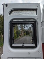
I started looking at the rear doors, since the rear lounge also converts to the bed in the Benivan and the doors were a noticeable source of cold night and day. Fortunately the plastic trim panels on the rear doors are simply held in place with plastic 'push rivets' which come out easily with a trim removal tool
PXL_20240425_182623955.jpg
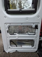
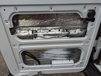
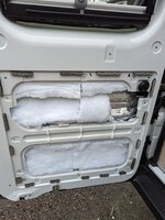
Taking off the panels reveals that the manufacturers insulated the van with an advanced technique - slap a few token bits of insulation where it's easy to do so and hope no-one notices...
PXL_20240404_101606261.jpgPXL_20240404_101610207(1).jpg
Lightweight self-adhesive foam insulation with a foil surface covered about 40-50% of the area of the door, although significant areas weren't stuck on properly, allowing air to get behind it and reducing it's value even further. No wonder it's cold by those doors at night!

I decided that I would use a denser 10mm self adhesive foam with foil surface against the metalwork where possible and then Dacron (Polyester) fleece to infill. Although various low price options are available on Amazon, some of the reviews suggest that it can be difficult to remove the backing paper from the adhesive, so I went with Dodo Thermo Liner Pro 10mm and Dodo Fleece from https://www.deadening.co.uk. Ordered online and arrived next day, although actually they are not far down the road from us in Wallingford.

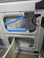
If you are converting a van from scratch and insulating it then you might be able to stick on big blocks of insulation at a time, but insulating the rear doors requires a jigsaw of small pieces cut to size and slotted into often difficult to reach parts of the metalwork. The enclosed vertical channels each side of the window are pretty much impossible to insulate properly but everything else is possible. Care needs to be taken where the mechanism of the door hinges and locking shouldn't be impeded. I also tried to avoid putting adhesive foam over the bolts/trim clips holding the external black trim and number-plate lighting etc to avoid issues if maintenance is required in future.

PXL_20240406_100216116.jpgPXL_20240406_104433145.jpg

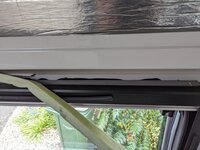
I also added extra insulation around the window frame and filled the voids with fleece. When refitting the plastic trim panels, I added 5mm foam strip on the rear around the edges to stop them rattling agains the metalwork.

We went away for a short trip to Weymouth the other week with only one rear door insulated - it was quite noticeable that the internal trim panels on the insulated door felt considerably warmer than those on the uninsulated one, which was pleasing - the insulation was having a useful effect in spite of the large amount of metal in the door being able to act as 'thermal bridging'. The door is also much less tinny sounding and shuts with a thud rather than a clang.

I've now done the second rear door and started on the sliding door (whoosh-bang). The sliding door had about the same level and quality of insulation as the rear doors - ie less than half the metal has insulation and more than half the insulation isn't stuck down properly...

PXL_20240425_082302179.MP.jpgPXL_20240425_082403754.jpg
The biggest challenge with the sliding door was removing the internal trim, which was screwed into place. The screw trim screws on the back end of the door cannot be accessed with the door closed (the kitchen units are in the way), and cannot be accessed with it wide open (the door is sitting too close to the side of the van), but can be undone with the door open a few inches - when the rear of the door has moved out from the side of the van but not back very far yet. Even so, a short, stubby, screwdriver or a right-angle bit holder come in handy!

I have been removing the manufacturer installed foam where it is not firmly stuck down and either re-sticking it using spray contact adhesive (won't move again!) or re-using it by cutting it up to add more insulation around the window frames.

Somewhere I have a handle to add to the sliding door to make it easier to close along with some rivnuts to mount it. Unfortunately I've put that somewhere safe for when I'm ready to install it and can't find it at the moment... Oh well, it will come to light soon...

After I've done the sliding door I plan to move on to the driver and passenger doors - more for the sound insulation properties there than the heat insulation - should also be a good opportunity to install a ProPlate on the drivers door to protect the lock.

cheers,

Robin
 

Join us or log in to post a reply.

To join in you must be a member of MotorhomeFun

Join MotorhomeFun

Join us, it quick and easy!

Log in

Already a member? Log in here.

Latest journal entries

Funsters who are viewing this thread

Back
Top