No that is not the same as the second board I altered. I would guess the relay you need to disable is top right in your pic. You could pop the cover off and do some testing…This one I meant to comment on sorry is this yours you took the insides out buddy ? I’m still having issues with mine I don’t want to touch just yet incase I do a lot of damage . But if this is what yours looks like so does mine

-
Rallies
New events -
Resources
Latest reviews
Navigation
Install the app
How to install the app on iOS
Follow along with the video below to see how to install our site as a web app on your home screen.
Note: This feature may not be available in some browsers.
More options
You are using an out of date browser. It may not display this or other websites correctly.
You should upgrade or use an alternative browser.
You should upgrade or use an alternative browser.
Swift split charge relay and habitation relay location help (1 Viewer)
- Thread starter Largejj
- Start date
seanwinder22
Free Member
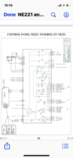
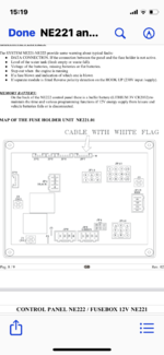
These are for anyone wanting the diagram to the nord ne221 fuse board  it clearly shows everything you need to check out the bottom image shows the split charge In b1 & b2 with the D+ signal built into the panel
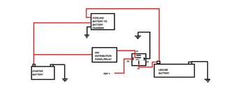
However jp4 socket 6 apparently is a D+ signal so the 5 pin relay should work I have also placed another image with a diagram I think it should look like from another thread .. but the relay is in between the leisure battery feed (not) the starter battery feed . Doing it the starter way your fridge won’t work when driving , but this way should also on the image of the relay it says ig ignition feed please read into this part . Which this is what I am doing now
I just wanted to get this diagram on the thread because I haven’t seen one yet
it clearly shows everything you need to check out the bottom image shows the split charge In b1 & b2 with the D+ signal built into the panelHowever jp4 socket 6 apparently is a D+ signal so the 5 pin relay should work I have also placed another image with a diagram I think it should look like from another thread .. but the relay is in between the leisure battery feed (not) the starter battery feed . Doing it the starter way your fridge won’t work when driving , but this way should also on the image of the relay it says ig ignition feed please read into this part . Which this is what I am doing now
I just wanted to get this diagram on the thread because I haven’t seen one yet
Attachments
Last edited:
seanwinder22
Free Member
These are for anyone wanting the diagram to the nord ne221 fuse board
However jp4 socket 6 apparently is a D+ signal so the 5 pin relay should work I have also placed another image with a diagram I think it should look like from another thread .. but the relay is in between the leisure battery feed (not) the starter battery feed . Doing it the starter way your fridge won’t work when driving , but this way should also on the image of the relay it says ig ignition feed please read into this part . Which this is what I am doing now
I just wanted to get this diagram on the thread because I haven’t seen one yet
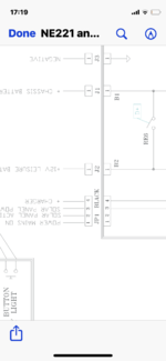
Yes the D signal is on jp8 pin 1These are for anyone wanting the diagram to the nord ne221 fuse board
However jp8 pin 1 is the only one you need apparently is a D+ signal so the 5 pin relay should work I have also placed another image with a diagram I think it should look like from another thread .. but the relay is in between the leisure battery feed (not) the starter battery feed . Doing it the starter way your fridge won’t work when driving , but this way should also on the image of the relay it says ig ignition feed please read into this part . Which this is what I am doing now
I just wanted to get this diagram on the thread because I haven’t seen one yet
Splice into this wire then you have the signal you need
or as above the ignition feed then the 70 amp 5 pin relay wired like in the image will be a great work around rather then destroying the split charge relay built in the panelI hope this helps anyone looking into this . It’s taken me weeks of searching
 rather then just destroy the split charge I wanted a bypass option
These are 100% the ne221 diagram too
The D+ signal is 100% jp4 pin 6 on the diagram
Hope this works for anyone
Subscribers do not see these advertisements
Last edited:
seanwinder22
Free Member
I now need some ideas please from you guys that did some amazing work above
It’s the ne221 and ne222 control panel again lol
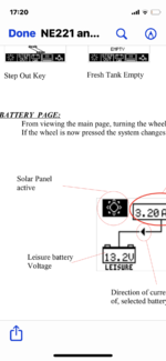
Apparently with the built in solar that must have come with the motorhome.. which is all now Victron but it was pwm
On the ne222 panel it used to show the solar icon like it does when on mains or voltages
I find this helpful as it also displays watts
all the wiring and sockets show on the diagram below
My question is … how would I go about now having the Victron mppt solar to still show on the ne222 panel ? Would it at some point have had a signal feed from the solar pwm to the fuse board and the 222 panel ?
Just like the Sargent charger px300 that Also uses a live signal feed that runs to the 222 panel showing it’s on mains hook up all images below show you
Any help or advise would be great
I would like to get this hooked up
On the diagram it’s jp1 shows mains and solar active solar power and charger
Thanks
It’s the ne221 and ne222 control panel again lol
Apparently with the built in solar that must have come with the motorhome.. which is all now Victron but it was pwm
On the ne222 panel it used to show the solar icon like it does when on mains or voltages
I find this helpful as it also displays watts
all the wiring and sockets show on the diagram below
My question is … how would I go about now having the Victron mppt solar to still show on the ne222 panel ? Would it at some point have had a signal feed from the solar pwm to the fuse board and the 222 panel ?
Just like the Sargent charger px300 that Also uses a live signal feed that runs to the 222 panel showing it’s on mains hook up all images below show you
Any help or advise would be great
I would like to get this hooked up
On the diagram it’s jp1 shows mains and solar active solar power and charger
Thanks
Attachments
seanwinder22
Free Member
Jp8 pin 1 not jp4Yes the D signal is on jp8 pin 1
Splice into this wire then you have the signal you need
I hope this helps anyone looking into this . It’s taken me weeks of searching
These are 100% the ne221 diagram too
The D+ signal is 100% jp4 pin 6 on the diagram
Hope this works for anyone
seanwinder22
Free Member
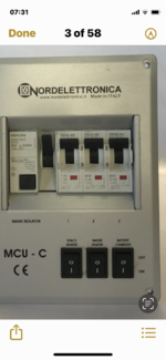
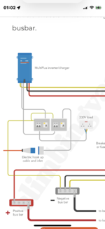
Does anyone know how I would wire the multiplus 12/1600/70 into the mcu-c in the image below ?
I do know the bottom socket is mains shore power all these sockets have x2 cables running to each socket
on the front of this breaker is for charger . Space heater . Water heater
I can not find a wiring diagram or manual for it tho
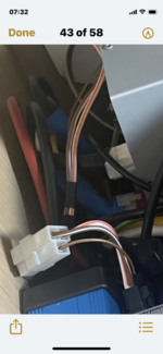
I have also taken a image of the back of the mcu wired in my motorhome which shows the yellow & white cable comes from 1 socket is the shore power cable maybe in and out ?? The black cables x2 in another socket which one of them goes to the Victron ip22 I have now but I’m not sure if this cable can just be taken out the ip22 now and straight into the multiplus ? this cable obviously is what was need for the ip22 to generate power ?
There’s another socket with x2 cables which must be for the space heater
I’m trying to figure out the ac in and out to get the multiplus wired in
I do know the bottom socket is mains shore power all these sockets have x2 cables running to each socket
on the front of this breaker is for charger . Space heater . Water heater
I can not find a wiring diagram or manual for it tho
I have also taken a image of the back of the mcu wired in my motorhome which shows the yellow & white cable comes from 1 socket is the shore power cable maybe in and out ?? The black cables x2 in another socket which one of them goes to the Victron ip22 I have now but I’m not sure if this cable can just be taken out the ip22 now and straight into the multiplus ? this cable obviously is what was need for the ip22 to generate power ?
There’s another socket with x2 cables which must be for the space heater
I’m trying to figure out the ac in and out to get the multiplus wired in
Subscribers do not see these advertisements
Attachments
Funsters who are viewing this thread
Total: 2 (members: 0, guests: 2)