My retro-fit Carver dual fuel blown air heating system - Pic-heavy thread! (1 Viewer)

RogerThat

LIFE MEMBER
May 20, 2016
1,128
991
North West
Funster No
43,198
MH
PVC
You may have seen my thread explaining my freezing cold bathroom (due to not having a blown air system) and the various ideas I was bounding around re fitting an electric towel rail in there to keep the chill off.

Anyway, the electric towel rail in my 'wet room' style bathroom probably wasn't a great idea and I headed off to research converting or upgrading my trusty Carver gas-only space heater in to a dual-fuel blown air system.

Turns out it appears to be a lot more simple than I first suspected.

I'll use this thread to document my retro-fit blown air system on my 1999 Swift Sundance and to highlight any pitfalls or gotchas that I encounter along the way, along with what parts are needed, costs, etc.

Here's the Carver heater in my MH, I forget the model number but it's the most basic one with just one dial to control the heat and one push button that you need to press a few times to get the fire to ignite.

UNADJUSTEDNONRAW_thumb_22.jpg


You can't see too well from that photo above, but there is a wardrobe directly above the heater, and my freezing bathroom is immediately to the left of that pic.

On the rear of the heater is a removable disc, I guess Carver make/made millions of these to keep costs down.

This disc will prise off, I've not removed mine as yet (will do nearer the time).

UNADJUSTEDNONRAW_thumb_21.jpg


Thanks to those of you in the other thread(s) that pointed me in the right direction for the various bits and pieces that I needed to get this job done.

As ever, I'm doing this on a budget. I'm fully aware that I won't be able to recover any money I invest in my old motorhome but I do want to make as many improvements to my motorhoming experience as I can so I see this as an investment in my future enjoyment and comfort levels more than anything else :)

So, with this in mind, it's my intention to use as many second hand / reclaimed parts as I can - eBay being my friend.

I'm not quite sure what the relationship with Carver and Truma is but there are a LOT of Truma parts on eBay, not so many Carver parts. Many seem to be interchangeable, especially where the ducting and outlets are concerned. However, I'm not sure about the motor assembly which connects to the rear of my heater as the Truma ones look significantly different in size and shape from that of the Carver ones.

With this in mind, my quest began for Carver-only parts.

It took a while but eventually eBay came up trumps with a Carver blown air heating kit (removed from a caravan) which also included the controls. The controls were important to me as I wanted this job to look as 'factory-fit' as I could so to have the heater controls match my existing (Clipsal-style) controls was almost essential.

So £99 quid later and I was the proud owner of this little lot.

s-l1600.jpg


It's a genuine Carver Fanmaster Warm Air Heater, complete with controllers and all the associated wiring looms. It even came with an operating manual.

What it didn't come with though, was an installation manual. Thanks to @Eddystone who pointed me in the right direction for that manual, I attach that manual to this post below for completeness.

I contacted the seller in advance, and from advice gained here that £99 was a bit pricy (I still personally think that was a fair price including controls, wiring, etc) I asked the guy if he would throw in 3x outlets, some pipe/ducting clips and some ducting. Sure enough, he did!

So here's a closer more detailed look at what I ended up with.

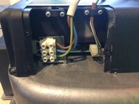
The fan motor assembly unit itself, two outlets and a 2Kw electric heater element contained within (this is how I convert to dual-fuel heating).

UNADJUSTEDNONRAW_thumb_2d.jpg


UNADJUSTEDNONRAW_thumb_2e.jpg


UNADJUSTEDNONRAW_thumb_31.jpg


UNADJUSTEDNONRAW_thumb_32.jpg


UNADJUSTEDNONRAW_thumb_33.jpg


I took this silver cover off and just had a quick blow out of any old dust. It was surprisingly clean inside there though.
 

Attachments

  • Carver_Fanmaster_Installation_Instructions.pdf
    2 MB · Views: 38
  • UNADJUSTEDNONRAW_thumb_2a.jpg
    UNADJUSTEDNONRAW_thumb_2a.jpg
    240.7 KB · Views: 397
OP
OP
RogerThat

RogerThat

LIFE MEMBER
May 20, 2016
1,128
991
North West
Funster No
43,198
MH
PVC
I also took the cover off the electrical cable point and disconnected the two cables.

One is the mains 240v power coming in (more on that later) the other is the cable which runs to the control panel (again, more on that later).

unadjustednonraw_thumb_2a-jpg.146728


Here's a closer look at the controls.

The one on the left is the main(s) power switch to turn on the electric 2kw heating element.

The one on the right is the controller which again I'll come back to later on.

UNADJUSTEDNONRAW_thumb_2b.jpg


Again, these match my exact style existing controls so will look great when mounted alongside the other ones.

Rear view.

UNADJUSTEDNONRAW_thumb_30.jpg


And here is the first of the 'gotchas'.

These controls will be mounted in the rear lounge area, on the side of the wardrobe. Which means the back of this control box is inside the wardrobe (again, where the existing controls are).

The problem here is, the existing control box for the hot water controls has a 'back box' on it, to cover the wires and keep things safe. This control panel has no back box.

If you're doing a similar mod, depending on where you install, this might not be a problem. For me though, it was, I can't have 240v wiring exposed in the wardrobe.

So back to eBay again and £7 quid later I was the proud owner of a (new, couldn't find a second hand one) Clipsal back box.

s-l1600.jpg


Also in my box of 'stuff' from the kit I bought was three outlets.

UNADJUSTEDNONRAW_thumb_2c.jpg


Again, the next 'gotcha' was that the guy didn't send me any back-nuts for them. Not sure what the correct term is, but there is a large nut which attaches to the back of these to stop them falling out and it also accepts the hose.

Back to eBay again!

For £3 quid each, I bought some rear nuts.

s-l1600-2.jpg


Also in my box of tricks was some ducting.

UNADJUSTEDNONRAW_thumb_2f.jpg


The guy had included three 1-meter lengths. Not much use really...

I can use one of them to run the very short distance in to the bathroom, but I also wanted two outlets in the rear lounge which will require more ducting.

FYI, this stuff isn't that cheap (new) and I couldn't find any decent second hand bits in a 4m length so I had to buy new. Nearly seven quid a meter!!! Blimey... We'll call that a gotcha too.
 
OP
OP
RogerThat

RogerThat

LIFE MEMBER
May 20, 2016
1,128
991
North West
Funster No
43,198
MH
PVC
I also treated myself to a brand new part.

s-l1600-3.jpg


Yup, a bright white outlet!

My entire bathroom is pure white plastic (as you'll see in later photos) and a beige outlet just wouldn't look right. This was £3.25 so not too bad a price either.

I also bought a 'lamella' (no idea what that means) but it's a louvered insert which I thought might keep some water out while the shower is being used.

s-l1600-4.jpg


Looks white doesn't it?

Alas, it's actually a nice shade of 'primer grey' :(

So I'll have to spray that white.

Ok, enough typing and uploading for one night, I now have all the parts I need to get the job done.

I started work on the job today, will post more photos in a day or two when I get a chance but I'll keep you posted as to progress, costs and gotchas throughout :)

Subscribers  do not see these advertisements

 
OP
OP
RogerThat

RogerThat

LIFE MEMBER
May 20, 2016
1,128
991
North West
Funster No
43,198
MH
PVC
Another update for you with some scene and context setting (y)

Here's a (debatably) better picture of the Carver 4000 heater.

IMG_8892.jpg


And here are my existing Carver hot water controls, in their classic Clipsal beige.

These are the controls I mentioned that I was keen to match in terms of style when doing this modification.

I will be mounting the new heater controls directly underneath these hot water controls.

IMG_8853.jpg


And to put the location of the controls in the rear lounge in to context, here's a slightly zoomed-out view.

IMG_8854.jpg


The heater from a different angle, and one of the bench seat bases in which I intend to install one of the three vents.

IMG_8856.jpg


The ducting will exit from behind this wall (just above where those pipes are now).

IMG_8855.jpg


Up the right hand side of the wardrobe you can see the existing wiring for the hot water controls and the back-box I mentioned in the earlier post - it was this back-box that my new heater controls came without - so I had to buy one to keep things nice and safe.

Also note the grey circuit breaker, we'll need to take this apart later to tap our new circuit in. There is a wooden panel covering the lower section of the wardrobe which just lifts out so you can get to the 12v fuses and charger (and also to the back of the gas heater).

IMG_8857.jpg


Closer up.

IMG_8858.jpg
 
OP
OP
RogerThat

RogerThat

LIFE MEMBER
May 20, 2016
1,128
991
North West
Funster No
43,198
MH
PVC
This post covers a series of pictures of the rear of the existing gas heater, things are going to be tight in there, I need to be a contortionist to get some of this job done.

IMG_8859.jpg


Peering in to the abyss.

IMG_8860.jpg


Deeper in.

IMG_8862.jpg


Lower left, thankfully the gas pipes head off in different directions which leaves me room to drill a big hole through the wall in to the bathroom. If the gas pipes didn't split and have this gap, my project would have rapidly stalled until I could find someone capable of making new gas pipes. Check yours first!

IMG_8863.jpg


Lower right, no such issues here, clear path through the wall to the bench seat on the right.

IMG_8864.jpg


Brighter photo of the rear in general. Here you can clearly see the silver disc which needs to be prised off the rear of the gas heater. There's a handy little hole just to the right of the disc in to which you can insert a heavy flat bladed screwdriver and break the disc off.

IMG_8865.jpg
 
OP
OP
RogerThat

RogerThat

LIFE MEMBER
May 20, 2016
1,128
991
North West
Funster No
43,198
MH
PVC
Right then, on to the installation itself, time to get our hands dirty now :)

First things first, I removed both the bathroom door and the wardrobe door. They open back-to-back on each other and they'd really get in the way.

IMG_8891.jpg


Much better (y)

I wasn't quite sure which order to do things in so apologies if these photos are jumbled up but I'll try and group the tasks together as I detail this.

First up, let's get the back box for the control panel mounted.

I applied a few strips of masking tape to the wall underneath the existing hot water controls. This allows you to draw all over it with pencil to your hearts content.

Be sure to measure up the INSIDE measurements of the back-box, not the outside measurements of the front of the control panel!

IMG_8869.jpg


If your OCD is anything like mine, you'll spend a long time measuring this to make sure it's exactly centred and very, very level :LOL:

Before you do anything else, check the REAR of the panel to make sure there's nothing behind it. I unscrewed my existing cable clips from the wall to generate some slack in the wires, then I used a bungee cord and pulled them back, away from the wall. We do NOT want to drill or cut through these!

IMG_8874.jpg


Once you're happy, drill a hole in each of the four corners. The hole needs to be large enough to accommodate the diameter of your jigsaw blades. I think this is about 10 or 12mm.

IMG_8872.jpg


My first surprise here when drilling the holes, this wall is double-skinned!

It's very thin ply, just a few mill, but then there's a gap of around 10mm, then another sheet of ply on the inside of the wardrobe. That's what I learned today.

Now get the jigsaw in each hole and cut as straight a line as you can ;)

The end result should then allow you to push the back-box through the new hole.

IMG_8873.jpg


Once you're happy the hole is the right size, pull the masking tape off the wall and the back-box can now be screwed in to place.

IMG_8887.jpg


Time for a brew.

Subscribers  do not see these advertisements

 
OP
OP
RogerThat

RogerThat

LIFE MEMBER
May 20, 2016
1,128
991
North West
Funster No
43,198
MH
PVC
Ok, while we're making a mess with drills and saws, we may as well keep on making a mess before getting the hoover out.

Time to cut some holes for the ducting outlets. Exciting :cool:

I want one in the all-important-freezing-bathroom and two in the rear L-shaped lounge (one in each seat base).

You'll know roughly where you want them to go, but it is essential that you do these next bits this way round. Let me explain.

Personally, I'd have liked the vent outlets as close to the floor as possible, problem is, behind the face of the bench seat is the timber framework which makes up the base itself. Yes, technically you could just drill straight through this, but you wouldn't want to, especially if it was an up-right piece.

Therefore, from behind, you can work out exactly how low you can go. Place a vent outlet there and draw around it. Then mark the centre.

IMG_8870.jpg


You'll need a tank cutter to make the hole cutting really easy. Try and use one just a couple of mill bigger than the rear of the vent outlet diameter.

IMG_8875.jpg


Now another important bit!

Do NOT drill from the inside, outwards.

You will bust up the nice facia of your bench seat at the tank cutter comes smashing it's way out the front.

Instead, what you need to do is from the inside of the bench seat, drill the pilot hole out the centre. Then stop.

Now take the drill and from the front, now you can drill back through the pilot hole, all the way through.

The end result should be a completely undamaged facia on the front.

IMG_8876.jpg


A quick test fit.

IMG_8877.jpg


Do the same on the other bench seat.

Sorted (y)

Time for another brew.
 
OP
OP
RogerThat

RogerThat

LIFE MEMBER
May 20, 2016
1,128
991
North West
Funster No
43,198
MH
PVC
Right, brew done, back to work.

Here's the other outlet in the other bench seat, and I also drilled the hole through to the wardrobe (rear of the gas fire).

IMG_8885.jpg


It was here I stumbled upon another gotcha.

I got so keen with my tank cutter drill bit that I failed to pay attention to the diameter of the ducting, which is actually a few mill wider than the diameter of the outlets.

This was an issue because when I (later) went to pass the ducting through to the wardrobe, it didn't bloody fit!!! The hole was too tight!

IMG_8894.jpg


In typical fashion, I didn't realise this until I'd drilled all the holes, hoovered up all the mess, tidied up, put the hoover away in the house, etc.

So I had to get the tank cutter out (a slightly bigger one) and enlarge the hole.

Which is where I knew a gotcha was coming!

Tank cutter bits rely on a pilot hole to keep things straight. I didn't have anywhere I could drill a pilot hole through as I'd already drilled a whacking great hole for the duct. This meant I had to freestyle the tank cutter enlargement. Not an easy task to be honest. Don't get caught out :)

That's the easy stuff done, the next hole warrants a post all to itself!

Subscribers  do not see these advertisements

 
Apr 27, 2008
11,842
14,071
Eastbourne East Sussex
Funster No
2,327
MH
Hymer low profile
Exp
Since 1972
Very good. I fitted one like this years ago (when it was the current model).

One point, which you may already be aware of, is that there should be one outlet that is permanently open. I used the washroom one. If all the vents are closed accidentally or otherwise, and you are running the electric element, the airflow will be blocked and the whole thing may over heat. You don't need a special outlet, just remove the flap from one of your existing ones.
 

hilldweller

LIFE MEMBER
Dec 5, 2008
605
36,109
Macclesfield
Funster No
5,089
MH
Zilch Mk1
Exp
From Aug 2007
I didn't have anywhere I could drill a pilot hole through as I'd already drilled a whacking great hole for the duct.

Not that I have ever done this you understand but I hear the trick is screw some scrap timber behind your great big hole.

Subscribers  do not see these advertisements

 
OP
OP
RogerThat

RogerThat

LIFE MEMBER
May 20, 2016
1,128
991
North West
Funster No
43,198
MH
PVC
Ok, the whole point of this modification was to make my bathroom warmer.

This meant drilling a 65mm hole in the wall of my bathroom.

My bathroom is a mixture of injection-moulded plastic and what looks like a custom made fibreglass shower tray.

I only get ONE shot at this.

Daunting does NOT cover it.

To make matters worse, I am really limited on where I can drill through the wardrobe due to the gas pipes on the back of the shower wall.

I took an air vent / duct outlet and placed it in the bottom of the wardrobe, in the gap between the gas pipes. I then tried to draw around it.

IMG_8879.jpg


I say 'tried' to draw around it. Bearing in mind the small gap behind the gas heater, and the fact it's quite far down, I had to somehow get one hand down there to hold the vent in place, another hand down there with a pencil, at which point I'm at such a bizarre angle I can't actually see a thing!

Thankfully, it worked out roughly ok!

IMG_8880.jpg


So that was it.

That was about the ONLY place I could drill this hole. I only had around 10mm on either side of the gas pipes.

The next hard part, was then trying to work out where this hole would appear in the bathroom.

My shower tray is flat on the first bit but then drastically curves to go under the sink. I was praying this hole would line up on a flat piece!

Through taking lots of measurements I worked out roughly where the hole would appear in the bathroom and I took the plunge.

I drilled a small pilot hole through the wardrobe and in to the fibre glass shower base.

That was it, I was past the point of no return :eek:

Thankfully, the pilot hole couldn't have been placed any better, it was perfect. Look closely to see the hole.

IMG_8882.jpg


By the way.

In case you were wondering why there's a plug in my shower tray... it's to keep all the plastic, wood and fibre glass dust out of my drain (y)

Heads up on another gotcha at this point. The wall from the wardrobe to the shower is also double skinned. However, the gap between the two on this side is huge, perhaps +50mm. Luckily I have a good selection of drill bits as the first hole I drilled through the bathroom wasn't with a bit long enough to actually appear in the bathroom :LOL:

Now it's time to cut a huge hole in the bathroom shower tray. This time, like the seat bases, we'll now drill from the front.

Heads up, fibreglass is BAD for your health. The dust it produces is super-fine. Wear PPE or spend the next two weeks coughing and having your eyes water.

Great big hole drilled!

IMG_8883.jpg


That's it, there is absolutely NO going back now :LOL:

Again, due to the huge depth of the gap in the wall, I had to drill the wardrobe hole from inside the wardrobe.

IMG_8884.jpg


Getting a bit draughty in there now (y)

IMG_8886.jpg


Not only time for a brew, but after that amount of fret and worry, a stiff drink was in order to calm the nerves!

With all the holes drilled and panels cut out, that'll do for today.

Will post more updates later in the week (y)
 
OP
OP
RogerThat

RogerThat

LIFE MEMBER
May 20, 2016
1,128
991
North West
Funster No
43,198
MH
PVC
>> Pic-heavy thread!

Sir, you are a gentleman. All the folk out there running on empty on their MiFi SIMs will be forever in your debt for those simple words.

No worries! I thought it would be worth a mention, especially as some pics here are very hi-res (y)

there should be one outlet that is permanently open. I used the washroom one. If all the vents are closed accidentally or otherwise, and you are running the electric element, the airflow will be blocked and the whole thing may over heat

An excellent point!

The Carver installation manual also warns of this, and it says the electric element will automatically shut down via a thermal cutout safety switch, but apparently that's a one-time event which has to then be undone / fixed via an authorised Carver repair centre. Unsure how true that is, but I don't really want to find out...

I plan on using the "lamella" grill/vent in the bathroom and much like yourself, have this as the permanently open one :)

Not that I have ever done this you understand but I hear the trick is screw some scrap timber behind your great big hole.

Ahhhh!! Why didn't I think of this?!

Yes, that would have probably worked quite well. I was thinking of screwing a sheet of hardboard over the front of the hole I incorrectly drilled but I thought I'd never line up the centre again. But yes, placing it on the back would have allowed me to see the centre point. That said, I have limited room to manoeuvre on the inside and fitting something on the inside would have been tricky. Do-able though, tip well noted thanks :D2
 

Margaritaman

Free Member
Oct 27, 2013
270
395
East Yorkshire
Funster No
28,763
MH
Low Profile C Class
Exp
since 2008
Enjoying follow this @RogerThat If you cut an undersized hole with your tank cutter again wonder if this would work to open out the hole.

Screw a baton of wood across the back of your undersized hole so the baton passes thru the centre of the hole. Now you have a "new" piece of wood to drill into with your pilot drill followed by the larger sized tank cutter, which will open out your undersized hole.

Never tried this but should work. Like you I tried free-styling with a tank cutter to open out a undersized hole. Boy did the cutter wander without the pilot drill !!

Looking forward to the next set of photos

Subscribers  do not see these advertisements


Anthea M

Free Member
Deceased RIP
Oct 18, 2015
9,501
165,143
Sheffield
Funster No
39,598
MH
Hobby
Exp
Since 2009
Wow I've loved reading and looking at the pictures . Great DIY skills and information for anyone wanting to do the same! A very professional job Rodger!
We take our heating for granted in the shower/loo and it's great for drying clothes and towels.
Thanks for taking the time and enjoy your warm shower room!!(y)

P.s I'm loving the purple mats!!
 

hilldweller

LIFE MEMBER
Dec 5, 2008
605
36,109
Macclesfield
Funster No
5,089
MH
Zilch Mk1
Exp
From Aug 2007
We have to leave a plug in the shower, there is no room for a water trap so it's there to stop the smells from the grey tank.

I'm not so sure about an air vent right in the shower. I guess you'll angle the pipe upwards to ensure it runs back into the shower.
 
OP
OP
RogerThat

RogerThat

LIFE MEMBER
May 20, 2016
1,128
991
North West
Funster No
43,198
MH
PVC
Enjoying follow this

Thanks (y)

Screw a baton of wood across the back of your undersized hole so the baton passes thru the centre of the hole. Now you have a "new" piece of wood to drill into with your pilot drill followed by the larger sized tank cutter, which will open out your undersized hole.

Never tried this but should work.

I think it would. Access would be tricky but could well be worth the effort.

The other issue I had where I'd not realised the hole for the pipe needed to be bigger than the hole for the vent was going out of the wardrobe and in to the bathroom. Going freestyle with the tank cutter from behind the gas fire, and only 10mm away from a gas pipe was seriously harrowing!!

Wow I've loved reading and looking at the pictures . Great DIY skills and information for anyone wanting to do the same! A very professional job Rodger!

Thanks very much :D2

P.s I'm loving the purple mats!!

Me too, that's the original carpet from 1999 too, it's that colour throughout (y)

I'm not so sure about an air vent right in the shower. I guess you'll angle the pipe upwards to ensure it runs back into the shower.

Yes, I have indeed. The pipe is at a sharp (well, as 'sharp' as this ducting goes) ninety degree upwards angle, you'll see some photos of this in a day or two :)

Plus too, I've got the 'lamella' (still no idea what that means) to fit. I'm hoping this will deflect 99% of the shower water away from the vent too.

This isn't my actual one, but it looks the same:

IMG_0173.JPG


I've done some more work on my install but I won't have time to post another update with photos tonight so stay tuned for the next episode in a day or two (y)

Subscribers  do not see these advertisements

 
OP
OP
RogerThat

RogerThat

LIFE MEMBER
May 20, 2016
1,128
991
North West
Funster No
43,198
MH
PVC
Hi everyone, thought I'd give you another update :)

On to the electrics now!

The electrics for this project are done in two stages. We've got the 240v side of things which manages the 2Kw heating element and the 12v side of things which drives the control panel and the fan of the motor (hence it can still work off grid, without EHU).

I'll kick things off with the 240v.

You've a couple of options here. If so desired, you could simply put a normal 13A mains plug on the heater and literally plug it in to a mains socket in your van.

However, I went the other route to keep things looking (and working) as original as possible.

First job was to run a cable from the consumer unit (the 'fuse box') of the motorhome up to the main power switch on the wall.

My unit has two MCBs (circuit breakers) on it, yours will be slightly different no doubt but the principal is the same.

One of my RCDs here manages the mains sockets in the van, the other powers the fridge and the existing water heater.

IMG_8893.jpg


To avoid tripping the RCD unnecessarily I opted to connect my heater to the mains outlet RCD as the only thing I use on mains is either the microwave or a low wattage travel kettle so trips should be a rare thing, if at all.

Alas, I didn't take any photos of this bit, sorry!

But very straight forward, two screws to remove the plastic cover from the consumer unit at which point it's quite clear how the MCBs are wired up and you'll see how to connect your new circuit in place.

So with that end of the wire connected, the other end of the new mains cable then runs up the wall to the rear of the new power switch on the wall.

IMG_8889.jpg


Electrical safety is paramount. Be sure to check for Earth continuity. I used a multimeter to make sure the earth pin on the switch was actually earthed (you can check this against most metal objects, the rear of the gas heater for example, or the earth pin of your EHU socket, or the earth pin on an existing mains socket in the van).

The red 'bar' on the switch you see above is the neon lamp which illuminates when the heater is turned on. Very straight forward to wire up, three wires in from the fuse box, three wires out to the heater itself.

Second job, as mentioned above, was to remove the existing mains cable from the fan heater assembly. You may remember mine had been cut by the guy who removed it from a caravan so it needed replacing anyway.

unadjustednonraw_thumb_2d-jpg.146723


Unscrew the cover and it's a simple matter of then removing the old mains cable.

The 2Kw electric element (well, technically it's a 1830w element) uses 8A so be sure to use mains cable of a suitable capacity. You'll also need a 10A or 13A fuse in the line somewhere too (mine is fused at the switch).

New mains cable installed:

IMG_8904.jpg


I also removed the other smaller cable (which goes off to the control panel on the wall) and wrapped a bit of tape around it to make it slightly wider as it was too thin for the cable grip to hold it in place securely, bit of a design flaw there really.

The other end of this cable now connects to the rear of the wall switch which we can now pop in place temporarily.

IMG_8890.jpg


Again, you should now check that you have full earth continuity from the fuse box, through to the wall switch, through to the metal casing of the electric heater.

So that's the mains side of things taken care of, on to the 12v side of things next (y)

Subscribers  do not see these advertisements

 
OP
OP
RogerThat

RogerThat

LIFE MEMBER
May 20, 2016
1,128
991
North West
Funster No
43,198
MH
PVC
Right then, without further ado (a-doooo?), on to the 12v electrics :)

There are two lots of cables for the 12v side of things.

One cable, the 'loom', contains three wires and has a moulded plug on each end. One end of this very simply plugs in to the heater itself (see the above photo, I won't repost it). The other end of that three-wire loom plugs in to the back of the control panel (you'll see the three pin connector here).

Screen Shot 2017-02-08 at 20.31.50.png


The other cable has two wires and these are the ones you'll need to power the control panel and the electric fan which blows the heat around.

Bizarre colours for these wires.

  • White / Orange Tracer = Earth
  • Blue / Black Tracer = +12v

Weird...

So the earth was an easy one, I simply crimped a ring connector on and screwed it to the charger in the wardrobe.

IMG_8921.jpg


For the +12v side of things, you'll need to tap in to an existing 12v circuit.

The electric fan motor is only 16w so it draws just 1.3A current. I have a small 12v fuse block mounted near the charger which controls various MH circuits such as lighting, water pump, etc.

Two of those circuits have 5A fuses in there and two have 10A fuses.

Again, to avoid possible trips, I tapped in to the to 10A circuit. Also, I added a separate 5A fuse to my fan circuit, to further isolate it from the other circuits.

You can just see the automotive fuse holder here:

IMG_8920.jpg


When choosing a circuit to tap your +12v in to, be sure you pick a circuit that supplies +12v when your van control panel is switched to both your Hab and your Cab battery. Don't wire it up to the charger for example because then it'll only work when on EHU ;)

The other end of your 12v cable now plugs in to the left hand side of the control panel (again, via a pre-moulded plug).

Screen Shot 2017-02-08 at 20.31.50.png


That's it, the 12v side of things is now complete (y)

Once you've tested that everything is working as it should be, the plastic covers can now be clipped in to place on the rear of the control panel / switches and the cables can be tidied up.

IMG_8928.jpg


Things are hotting up now!

IMG_8930.jpg


And for stylistic purposes, here's the new blown air heater controls alongside the existing hot water controls.

IMG_8929.jpg


Close up.

IMG_8931.jpg


The next steps will be to actually install and mount the heater unit itself, and then to get some ducting pipework in place. I can see one potential gotcha already in that the confined space will prove tricky to get the pipe from the heater in to the bathroom, but I've a trick up my sleeve to help me there, which I'll explain on the next lot of posts.

Will post more updates soon!
 

Minxy

LIFE MEMBER
Aug 22, 2007
32,646
66,526
E Yorks
Funster No
149
MH
Carthago Compactline
Exp
Since 1996, had Elddis/Swift/Rapido/Rimor/Chausson MHs. Autocruise/Globecar PVCs/Compactline i-138
... I can't wait for you to get it all sorted and have a good old 'blow'!!!!(y)
 

Louis

LIFE MEMBER
Mar 29, 2016
1,204
982
Anglesey
Funster No
42,191
MH
Fiat Ducato Auotrail
Exp
6 Months with motorhome(35 years tugging)
Right then, without further ado (a-doooo?), on to the 12v electrics :)

There are two lots of cables for the 12v side of things.

One cable, the 'loom', contains three wires and has a moulded plug on each end. One end of this very simply plugs in to the heater itself (see the above photo, I won't repost it). The other end of that three-wire loom plugs in to the back of the control panel (you'll see the three pin connector here).

View attachment 147194

The other cable has two wires and these are the ones you'll need to power the control panel and the electric fan which blows the heat around.

Bizarre colours for these wires.

  • White / Orange Tracer = Earth
  • Blue / Black Tracer = +12v

Weird...

So the earth was an easy one, I simply crimped a ring connector on and screwed it to the charger in the wardrobe.

View attachment 147195

For the +12v side of things, you'll need to tap in to an existing 12v circuit.

The electric fan motor is only 16w so it draws just 1.3A current. I have a small 12v fuse block mounted near the charger which controls various MH circuits such as lighting, water pump, etc.

Two of those circuits have 5A fuses in there and two have 10A fuses.

Again, to avoid possible trips, I tapped in to the to 10A circuit. Also, I added a separate 5A fuse to my fan circuit, to further isolate it from the other circuits.

You can just see the automotive fuse holder here:

View attachment 147196

When choosing a circuit to tap your +12v in to, be sure you pick a circuit that supplies +12v when your van control panel is switched to both your Hab and your Cab battery. Don't wire it up to the charger for example because then it'll only work when on EHU ;)

The other end of your 12v cable now plugs in to the left hand side of the control panel (again, via a pre-moulded plug).

View attachment 147194

That's it, the 12v side of things is now complete (y)

Once you've tested that everything is working as it should be, the plastic covers can now be clipped in to place on the rear of the control panel / switches and the cables can be tidied up.

View attachment 147197

Things are hotting up now!

View attachment 147198

And for stylistic purposes, here's the new blown air heater controls alongside the existing hot water controls.

View attachment 147199

Close up.

View attachment 147200

The next steps will be to actually install and mount the heater unit itself, and then to get some ducting pipework in place. I can see one potential gotcha already in that the confined space will prove tricky to get the pipe from the heater in to the bathroom, but I've a trick up my sleeve to help me there, which I'll explain on the next lot of posts.

Will post more updates soon!
Well done very professional !

Subscribers  do not see these advertisements

 
Sep 23, 2013
2,585
8,773
Lincs
Funster No
28,231
MH
Globecar Campscout
Exp
Since 2008 (started in a VW T4 campervan)
>> Pic-heavy thread!

Sir, you are a gentleman. All the folk out there running on empty on their MiFi SIMs will be forever in your debt for those simple words.
Hear, Hear! My thoughts exactly! (y)

Pictures are an essential part of this forum & very welcome, but it is useful to be forewarned when travelling.
 
OP
OP
RogerThat

RogerThat

LIFE MEMBER
May 20, 2016
1,128
991
North West
Funster No
43,198
MH
PVC
Hi everyone, time for another update (y)

Now for one of the fiddliest bits of the entire installation.

Well, second fiddliest, the first was drilling the hole in to the bathroom without damaging the gas pipes in the wardrobe.

Things are taking shape now, all the holes are drilled, the 12v and the 240v electrics are all done, time to get some ducting installed!

As a reminder, the heater has two outlets, one on each side. My plan is to have one outlet run directly in to the bathroom and the other outlet will feed the two ducts in the lounge area.

unadjustednonraw_thumb_2d-jpg.146723


You can see two little holes on each outlet in the above photo. They are there so that when you insert the ducting pipe you can then put a little self-tapping screw through the hole to hold the ducting hose in place, you don't want it falling out.

The fiddly part of the duct running in to the bathroom is purely down to a lack of space (for me to manoeuvre, behind the heater).

I attached the fan motor temporarily in place with just one screw so I could see how things looked and try to work out how best to do this.

IMG_8908.jpg


Remember, the bathroom is on the left, I have VERY little room down the left hand side there.

It would be almost impossible for me to attach the ducting pipework to the outlet in the bathroom then try to bend the ducting to connect it to the heater, there's just not enough room to get my arm down there and the very short distance from the bathroom vent to the heater itself means there is almost no free movement in the ducting hose itself.

I removed the heater again and installed the outlet in to the bathroom and I also attached the rear nut. This in itself was quite tricky as I had to try and hold the front of the outlet in the bathroom with one hand and with the other hand I had to reach down inside the wardrobe and try to reach in to the wall cavity to attach the nut on the rear. Again, another reason to take both doors off!

IMG_8905.jpg


I decided it would then be best to measure up a piece of ducting pipework and attach it to the heater first, then lower the whole assembly in to place and as I was lowering, I intended to feed the ducting through the wall and have it land on the back of the outlet.

Easy, eh? (n)

You may remember I had a few old bits of pipework supplied with the heater so I was able to trim 20min slices off at a time in order to get the pipe to the exact length I needed it (you can see the trimmed bits at the top).

M0vcvCAIRyiHUYocip+ASQ_thumb_87.jpg


This was a lot of trial and error. It would be impossible to actually measure the length required so there was a lot of test fitting, removing, cutting, test fitting again, removing again, cutting again, test fitting again... you get the idea.

What I ended up with was a piece of pipe that was the perfect length that one end could be screwed in place on the heater itself, the other end could be connected to the back of the backroom duct as I lowered the whole assembly down in to place.

IMG_8902.jpg


You don't want that bit of pipe to long as you won't then get the heater in to place. You also don't want it too short as it'll fall off the back of the vent in the bathroom.

Looking good!

IMG_8910.jpg


I put my camera phone down behind the heater and took about 10x photos at random angles (again, I can't actually SEE down there) so you can see how it connects on the rear.

IMG_8896.jpg


Time to paint that grey lamella white. Nobody would see the back of it, but again my OCD kicked in and it forced me to paint the back too :LOL:

IMG_9021.jpg


I only gave the back one coat but I gave the front of the vent four coats (probably overkill).

IMG_9028.jpg


To fit the vent, you need to remove the flappy bit (that's my technical description) from the original vent. It just pops out as it's held in place with a spring.

The lamella then just clips in to the outlet.

IMG_9036.jpg


As as @Reallyretired mentioned earlier, this also now goes to serve the 'one vent permanently open' factor to prevent things overheating in case all the vents were somehow accidentally all closed (y)

IMG_9035.jpg


So that's the bathroom side of things all finished. Hurrah!

Just the two outlets in the lounge area to go :D2

I'll post another update on the lounge area soon as there are some points to note regarding the various ducting runs, the 'drop off' in air flow on distance vents and some interesting notes of observation when I tested T-piece vs Y-piece ducting splits.

Really taking shape now (y)
 

ambulancekidd

Funster
Sep 23, 2014
10,365
28,388
Ayrshire Scotland
Funster No
33,478
MH
Swift Kon-Tiki 640
Exp
Since 1964 Gosh that makes me feel old.
Can I ask what the compressor is for? I noticed it down on the floor behind the heater & the gauges on the wall next to your hot water controls.

Subscribers  do not see these advertisements


TheBig1

LIFE MEMBER
Nov 27, 2011
17,630
43,252
Dorset
Funster No
19,048
MH
A class
Exp
many many years! since I was a kid
Can I ask what the compressor is for? I noticed it down on the floor behind the heater & the gauges on the wall next to your hot water controls.
the gauges are for air suspension so I guess that
 
OP
OP
RogerThat

RogerThat

LIFE MEMBER
May 20, 2016
1,128
991
North West
Funster No
43,198
MH
PVC
Approaching the end now, only another post or two required :)

Time now to run the ducting out the right-hand side of the wardrobe and over to the two outlets in the rear lounge, one under each sofa.

Thankfully, plenty of wiggle room on the right hand side of the heater!

IMG_8913.jpg


In the above photo, you can just see the ducting outlet on the edge of the heater, you can also see the 'cavity' wall of the wardrobe on the right hand side.

The first duct, under the first sofa (mine is an L-shaped lounge by the way!) is very near to the wardrobe so we just need a short run for this one.

However, we then need to run ducting to the second vent.

You've a couple of options here in terms of splitting the pipe, a T-piece or a Y-piece. Well, two different T-pieces to be precise.

Here's what's called an "equal T" piece. So called, because funnily enough, the splits on the T are equal :rolleyes:

s-l1600-3.jpg


You also have what's called an "outlet T" piece. Slightly different from the above pic because this one allows you, yup you guessed it, to connect a ducting outlet vent directly to it. In this case, you then do not need a rear locking nut on the vent as the vent screws directly in to the T-piece.

s-l1600.jpg


Last but not least, we have the Y-piece. I'm not going to explain why it's called a Y-piece as a picture says a thousand words, right? :LOL:

s-l1600-2.jpg


The type of connectors you use will be somewhat determined by your own installation requirements.

In my case, I was hoping to use the outlet-T but as you'll see in a photo below, the angle of the pipe would have been too great. This meant I had to use either the equal-T or the Y-piece. Again, thankfully, I had some old bits of ducting I could chop up in order to conduct some experiments.

What I found was that using the equal-T the air flow seemed carry on past the outlet that was branches from the "T" and the outlet didn't seem to have much air flow / pressure coming out of it. Physics I guess..

The Y-piece however, as you can probably imagine, provided a much more even air flow out of both vents.

So, I opted for the Y-piece. Something to bear in mind though, the equal-T would be very useful if the second or last outlet was some distance away as the overall pressure in the ducting could be maintained.

Anyway, back to the install.

I created a Y-piece of ducting. The long section on the left runs through the wall and connects to the heater, the short section connects to the first vent/outlet. The unconnected end will feed the ducting that goes to the other outlet in the other sofa.

IMG_8914.jpg


This then connects in place like so.

IMG_8915.jpg


And from a looking at it from behind. Note the now-enlarged hole where I mentioned earlier the 'gotcha' with the tank cutter bit I used not being large enough. You can also see in this photo one of the locking nuts that attach to the rear of the outlet vent.

IMG_8916.jpg


It was then time to use the longer ducting that I bought to run to the other sofa.

In this photo, you can also see I put a little self-tapping screw in to each piece of the ducting connected to the Y-piece to stop anything disconnecting itself.

IMG_8936.jpg


Making sure of course the pipe was not mounted so high as to fowl the sliding section of the seat base.

IMG_8938.jpg


The ducting then runs behind the seat base and past the Carver hot water tank/heater (excuse the mess).

IMG_8942.jpg


I've hit the forum image limit per post.... give me a moment while I create another reply!

Subscribers  do not see these advertisements


Join us or log in to post a reply.

To join in you must be a member of MotorhomeFun

Join MotorhomeFun

Join us, it quick and easy!

Log in

Already a member? Log in here.

Latest journal entries

Funsters who are viewing this thread

Back
Top