Homebrew solar tracker. (1 Viewer)

OP
OP
Snowbird

Snowbird

LIFE MEMBER
Apr 24, 2009
11,818
22,346
Liverpool.
Funster No
6,422
MH
Fifth wheel.
Exp
Since 11-05-2000
Just played about with our friend the Pololu LSM303DLH Compass. Without calibration I simply measured the x,y and z magnetic field strength and plotted them on a 3D graph. I then moved the unit around in as many directions as I could contort myself and repeated. An ideal compass in a static magnetic field (such as that created by the earth's magnetic field) would trace out a perfect sphere.

Here's what we get:
lsm303.jpg


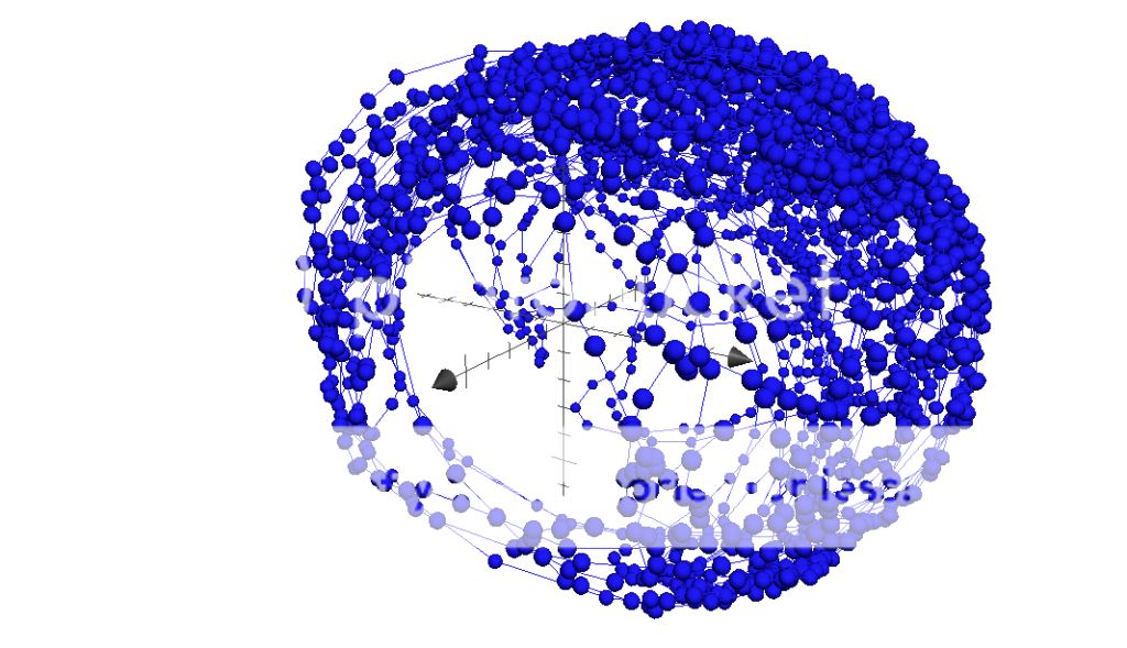
(axes are magnetic field strength in arbitrary units in the Cartesian x,y,z direction)

Our sphere is a little bit rugby ball shaped but I don't think we can complain too much. I can't see any horrendous outliers either so I think the compass might be reasonably reliable.

Will calibrate to correct the aberration. We really need to compare to a good quality digital or analogue compass and experiment with the effect caused by nearby ferrous materials.
 
OP
OP
Snowbird

Snowbird

LIFE MEMBER
Apr 24, 2009
11,818
22,346
Liverpool.
Funster No
6,422
MH
Fifth wheel.
Exp
Since 11-05-2000
Hello funsters!

We'll we finally got round to mounting the panel on our Oyster arm and we're pretty pleased with the results.

First we added some aluminium cross beams to the back of the solar panel spaced so that arm of the Oyster would fit comfortably between them.

mount1.jpg


We doubled up on the locknuts here.

mount2.jpg


As you can see the arm fits nicely between these cross beams with the top wings resting on the beams and the two lugs near the bottom supporting the arm. The very bottom of the arm also sits nicely onto the edge of the solar panel.

mount3.jpg


We added aluminium straps across the arm and bolted them until they bowed, firmly holding the arm in place. With just one of these straps in place we could easily lift the panel up by the arm without it moving an inch.

mount4.jpg


mount5.jpg


We mounted the whole lot back on the Oyster making sure that the panel was level when the arm was in the home position. This means that when the unit is turned off it should perform no worse than a panel mounted on the roof. The clearance between the arm/staps/beams and the fibre glass Oyster base when the solar panel is levelled is pretty decent, we're not anticipating any problems here but of course we'll have to carefully watch the full range of motion to be sure.

mount7.jpg


The final product actually looks a bit like a solar tracker! We used a level to check that in the "home" position the panel is pretty level.

mount9.jpg


mount10.jpg


There is some play in the panel and arm but the Oyster seems quite comfortable supporting the weight. The whole arrangement does not feel considerably heavier than the original satellite dish and LMB. The Oyster is designed to battle pretty high winds without too much trouble and our guess is that it will perform ok with the panel on it.

Unfortunately, our little control circuit is not in one piece at the moment as we had to dismantle it for testing the compass and GPS code properly. Hopefully in the next few days I can put this back together, tweak the PWM duty cycle to ensure we've got enough umpf to lift the panel comfortably and test out our tracker! I'm interested to see how it performs with the full weight on it, let's hope that gearing saves us.
 

Theonlysue

LIFE MEMBER
Sep 14, 2009
6,104
7,383
Essex
Funster No
8,456
MH
As Executive 50th an
Exp
Not long enough!
homebrew tracker

Looking forward to the final testing.
Keep up the good work. It's made interesting reading ::bigsmile:

Subscribers  do not see these advertisements

 
OP
OP
Snowbird

Snowbird

LIFE MEMBER
Apr 24, 2009
11,818
22,346
Liverpool.
Funster No
6,422
MH
Fifth wheel.
Exp
Since 11-05-2000
Ste here...

I rebuilt the control circuit and we decided to test the unit out with the panels mounted. It is a little top heavy so at first since it is not secured down it nearly threw itself across the room, fortunately, Dave managed to grab the thing before it fell and we can report no damage :ROFLMAO:. He has quick wits for an old man!

Here's a video of it in action, it is running the same program as the last video we showed but we had to up the vertical motor power to just over 50% (rather than just over 25% as in the previous video). It returns home just a little bit hot but we think the behaviour is ok :thumb:.

Let us know your thoughts... time for me to get some sleep...

[ame="http://www.youtube.com/watch?v=WRky41k-D8o"]Arduino Solar Tracker (Alpha 2) - YouTube[/ame]
 
OP
OP
Snowbird

Snowbird

LIFE MEMBER
Apr 24, 2009
11,818
22,346
Liverpool.
Funster No
6,422
MH
Fifth wheel.
Exp
Since 11-05-2000
Well am pretty much impressed with this project as are quite a number of people worldwide, as this thing has been number one on Google for months. I know its been a fairly drawn out affair but I hope you have had as much fun from watching it develop as we have making it.
I just hope we can have the dining room returned in time for Christmas. Before he gets his teeth into another "impossible" project, like homebrew self seeking internet access :whatthe:. Watch this space :thumb:
 

Geo

Trader - Funster
Jul 29, 2007
11,757
14,565
Mansfield,Notts
Funster No
35
MH
Autotrail Tracker FB
Exp
45 +years with breaks
I too have been impressed with your endeavours and tenacity, whilst you have had fun I have looked at it from a business point of view.
I conclude the first unit could be on the shelves for Christmas
Given research and development cost on the prototype it should retail at circa £98,655,67p plus vat
I would like to order 6000 units and will expect my Funsters discount and a good trade price:ROFLMAO::ROFLMAO::ROFLMAO:
Geo

Subscribers  do not see these advertisements


hilldweller

LIFE MEMBER
Dec 5, 2008
605
36,109
Macclesfield
Funster No
5,089
MH
Zilch Mk1
Exp
From Aug 2007
Let us know your thoughts... time for me to get some sleep..

It's incredibly satisfying when your machine comes to life, 30 years of it and the satisfaction never diminished. Of course when your whole livelihood depends on it, part of it is relief.
 

gummifisch

Free Member
Jan 30, 2015
2
0
Germany
Funster No
34,937
MH
Eura Mobil 690HB
Exp
2014
@Snowbird

Hello,
thanks for sharing your great work.
I use your code for rebuild an old analog Oyster to watch digital TV and i am sure it will work.
I take the MonsterMoto Shield with two VNH2SP30 an rewrite the DualVNH5019 Library
so that i can use i with MonsterMoto.
I have a second Arduino with GPS an LCD for changing satellites, visualization, calculation and
manual control.
The dish uses other motors an other Hall-IC.
I found out how many pulses i have per deg. and positioning works fine.
I am not using the wormFactor (set to zero), because i don't understand it.
Without the wormFactor the dish will scratch over the roof.
Can you explain how this Factor is working?

Greeting from Germany
Gummifisch

(Sorry for rusty English)
 
OP
OP
Snowbird

Snowbird

LIFE MEMBER
Apr 24, 2009
11,818
22,346
Liverpool.
Funster No
6,422
MH
Fifth wheel.
Exp
Since 11-05-2000
@Snowbird

Hello,
thanks for sharing your great work.
I use your code for rebuild an old analog Oyster to watch digital TV and i am sure it will work.
I take the MonsterMoto Shield with two VNH2SP30 an rewrite the DualVNH5019 Library
so that i can use i with MonsterMoto.
I have a second Arduino with GPS an LCD for changing satellites, visualization, calculation and
manual control.
The dish uses other motors an other Hall-IC.
I found out how many pulses i have per deg. and positioning works fine.
I am not using the wormFactor (set to zero), because i don't understand it.
Without the wormFactor the dish will scratch over the roof.
Can you explain how this Factor is working?

Greeting from Germany
Gummifisch

(Sorry for rusty English)

Hi there, thanks for the feedback. I will pass your remarks on to my semi tame professor, who is now working in the Max Planck institute in Munich. Am sure he will appreciate your kind remarks.

Subscribers  do not see these advertisements

 
OP
OP
Snowbird

Snowbird

LIFE MEMBER
Apr 24, 2009
11,818
22,346
Liverpool.
Funster No
6,422
MH
Fifth wheel.
Exp
Since 11-05-2000
@Snowbird

Hello,
thanks for sharing your great work.
I use your code for rebuild an old analog Oyster to watch digital TV and i am sure it will work.
I take the MonsterMoto Shield with two VNH2SP30 an rewrite the DualVNH5019 Library
so that i can use i with MonsterMoto.
I have a second Arduino with GPS an LCD for changing satellites, visualization, calculation and
manual control.
The dish uses other motors an other Hall-IC.
I found out how many pulses i have per deg. and positioning works fine.
I am not using the wormFactor (set to zero), because i don't understand it.
Without the wormFactor the dish will scratch over the roof.
Can you explain how this Factor is working?

Greeting from Germany
Gummifisch

(Sorry for rusty English)

Ste sent me this via email which I have copied here for your assistance.

Hey,

I am very happy to hear you are using my work! I wish you the very best of luck with the project. Please do keep us all updated on this thread with what you are doing, I am very interested.

Firstly, I think your project sounds like a great idea. If you control the unit yourself you will be able to upgrade it forever.

Controlling the motors is difficult, so, well done on figuring this out. Really impressive stuff. You said that your unit uses different motors and a different Hall-IC to mine. Could you tell me more about the motors and the Hall-IC?

Most importantly: You must wire your motors so that moveM1 moves the machine horizontally and moveM2 moves the machine vertically or the code will not work! Secondly, I found that my arduino was unable to count pulses accurately if I move both motors simultaneously (I suspect that the interrupts occur too frequently) so I opted only to move one motor at a time. If you are trying to move both motors at the same time you may find that the pulse counting becomes very inaccurate and you lose track of where the arm is, so I advise against that. Finally, in my oyster at least the vertical limit switch was not where I would like it, here the design seemed flawed, we took our unit apart and moved the limit switch to a "sensible" place. I explain where I think it should be (very badly) here: , with this limit switch in the place I suggest it should be possible to prevent the machine from hitting the roof even if the calculations done in the code become inaccurate.

Now, if you set the wormFactor to zero I would expect the unit to try to crash into your roof, as you have described. Let us try to fix this.

As explained in the code (OysterTrack.cc Line 37) the wormFactor should be set to the number of pulses moved vertically per 360 degrees moved horizontally. To calculate this number for your machine do the following:
1) Put the machine in the "home position", both limit switches should be pressed. This is the position the machine would return to when "off".
2) Use moveM1(int pulses) to move the arm horizontally through a full 360 degree rotation. You will notice that as the machine moves horizontally the arm also moves up vertically!
3) Use moveM2(int pulses) to move the arm vertically down until it is level again, count the pulses required to do this.
4) !!! Raise the arm vertically back up at least as many pulses as you moved it down !!! <--- if you do not do this you will damage your roof.
5) Rotate the arm horizontally through a full 360 degrees in the opposite direction as in step 2 to return the machine to the "home position".

The number of pulses you must moveM2 down in step 3 to return the arm back to the level position is the "wormFactor". Insert this number in OysterTrack.cc Line 37 and provided you have set "maxHorizontal" and "maxVertical" correctly you can then use moveToAngle(float horizontal, float vertical) to position your machine however you like! Job done.

Now, I will attempt to explain why the wormFactor is required at all. You should probably be aware that it took me many hours to solve this problem and although I think my solution is elegant it is not particularly easy to understand.

The vertical motion of the Oyster unit is controlled by a "worm drive". This consists of a threaded screw which points vertically and a gear that interlocks with the threaded screw. Here is a youtube video of a worm drive: . The critical thing to understand is that as the screw rotates so does the gear that is interlocked, this is how the Oyster unit moves the arm vertically. The next thing to understand is that as the gear moves horizontally around the screw (even if the screw does not rotate) then the gear rotates! Because the gear interlocks the screw if the gear rotates around the screw it is equivalent to the screw rotating... so the arm moves vertically!

This explains why in step 2 above the arm moved up vertically! The screw stayed still and we moved the arm horizontally around the screw so it also moved UP vertically.

Now, we do not want the arm to move up vertically when we are trying to move horizontally so it is clear that we have to counteract this vertical motion this is why we need a wormFactor. How does it work? If I want to move only horizontally I must first use motor 1 to move horizontally and then use motor 2 to move the arm vertically back down however many degrees it moved up by due to the worm drive.

A typical horizontal movement might happen like so:
1) Move from 0 degrees horizontal to 180 degrees horizontal. Due to the worm drive we have moved 10 degrees up vertically.
2) Move from 10 degrees vertical to 0 degrees vertical.

We have now moved only horizontally through 180 degrees. Get it?

Now for the complicated bit. If you are moving horizontally in a clockwise direction the arm moves up. If you are moving horizontally in an anti-clockwise direction the arm moves down. Thus, if we are moving clockwise we may accidentally go beyond the vertical limit of 110 degrees and damage the machine. Alternatively if we are moving anticlockwise we may go beyond the vertical limit of 0 degrees and damage your roof :p! Additionally, if the machine is at vertical 0 degrees and you request clockwise movement you can not move vertically down first then horizontal as you will go below 0 degrees. Equally, if the machine is at vertical 110 degrees and you request anti-clockwise movement you can not move vertically up first or you will go beyond the vertical limit. The trick is to order the horizontal/vertical movements in such a way that the machine stays within the limits for all possible requested positions from all possible positions! This is a mathematics problem. If you look at lines 142-175 of MotorControl.cc you can see my solution to this problem, I think I solved it in such a way that the arm always makes the minimum number of moves.

Hope this helps! If something is unclear or you need any further help please contact me again!
 

gummifisch

Free Member
Jan 30, 2015
2
0
Germany
Funster No
34,937
MH
Eura Mobil 690HB
Exp
2014
Thanks a lot for your discription.
Now i understand how the worm drive work and
i realised that i don't need the worm corretion at all.
My dish is not similar to yours (i think mine is a little bit older).
The horizontal and vertical direction works seperate, so i will
kick out the correction and just make a vertical min. limit.
Then my LNB arm will not scratch the roof.

When it works i will post photos or a video.
 
Aug 6, 2013
11,953
16,570
Kendal, Cumbria
Funster No
27,352
MH
Le-Voyageur RX958 Pl
Exp
since 1999
I must admit I was surprised when IBM introduced water cooled mainframes donkeys years ago - but they worked OK ::bigsmile:

To my surprise I ended up with water cooling on my PC. I was building it when I realised I'd forgotten to order a CPU cooler. So I went down to the local computer shop (that I never use because it's expensive) and they persuaded me to use a water cooler on the basis that it would be very quiet (which it is). They've come a long way since their early geeky start (water coolers not my PC shop) and mine was a sealed package, pre-filled, with a lump with built-in pump that sits on the CPU, and a radiator & fan that fits over an existing fan outlet in the case. So all I had to do was screw it in & plug its connector onto one of the motherboard fan connectors.

Subscribers  do not see these advertisements


PeteH

Free Member
Nov 22, 2007
6,853
9,030
East Riding of Yorkshire
Funster No
900
MH
Rapido, 999M.
Exp
18+yrs plus 25+Towing
I like this thread. Its Geeky and Technically challenging, and keeps the brain from going to mush. Some years back sat on my posterior in Spain with a large glass of Rioca. I thought?. What if I just hinge both sides of the solar panel, and then make the pins removable? split pins would deal with them coming loose at inopportune moments! I could then raise whichever side was facing most south? which would give me the facility to angle the panel to get the maximum "rays" at any time of year?. It only need to be used, winter time, and on long term "boon-docking"?. On the road the alternator takes care of Battery charging.
 
OP
OP
Snowbird

Snowbird

LIFE MEMBER
Apr 24, 2009
11,818
22,346
Liverpool.
Funster No
6,422
MH
Fifth wheel.
Exp
Since 11-05-2000
KISS !

Our TV aerial is the clue to a nice simple solution. It rotates, it tilts, it's light and almost nothing to go wrong.

Ahh, but if everyone had that thought process Brian there would be little use for your TV aerial as the TV would not have been invented :D.

Subscribers  do not see these advertisements

 
  • Like
Reactions: DBK

PeteH

Free Member
Nov 22, 2007
6,853
9,030
East Riding of Yorkshire
Funster No
900
MH
Rapido, 999M.
Exp
18+yrs plus 25+Towing
Ahh, but if everyone had that thought process Brian there would be little use for your TV aerial as the TV would not have been invented :D.


Ah! The days of John Logie Baird eh?. Mechanical T-V. Who`d have though it!!! Just imagine a rotating dustbin lid with holes in.???

Pete
 
Aug 6, 2013
11,953
16,570
Kendal, Cumbria
Funster No
27,352
MH
Le-Voyageur RX958 Pl
Exp
since 1999
Hello funsters!

We'll we finally got round to mounting the panel on our Oyster arm and we're pretty pleased with the results.

First we added some aluminium cross beams to the back of the solar panel spaced so that arm of the Oyster would fit comfortably between them.

mount1.jpg


We doubled up on the locknuts here.

mount2.jpg


As you can see the arm fits nicely between these cross beams with the top wings resting on the beams and the two lugs near the bottom supporting the arm. The very bottom of the arm also sits nicely onto the edge of the solar panel.

mount3.jpg


We added aluminium straps across the arm and bolted them until they bowed, firmly holding the arm in place. With just one of these straps in place we could easily lift the panel up by the arm without it moving an inch.

mount4.jpg


mount5.jpg


We mounted the whole lot back on the Oyster making sure that the panel was level when the arm was in the home position. This means that when the unit is turned off it should perform no worse than a panel mounted on the roof. The clearance between the arm/staps/beams and the fibre glass Oyster base when the solar panel is levelled is pretty decent, we're not anticipating any problems here but of course we'll have to carefully watch the full range of motion to be sure.

mount7.jpg


The final product actually looks a bit like a solar tracker! We used a level to check that in the "home" position the panel is pretty level.

mount9.jpg


mount10.jpg


There is some play in the panel and arm but the Oyster seems quite comfortable supporting the weight. The whole arrangement does not feel considerably heavier than the original satellite dish and LMB. The Oyster is designed to battle pretty high winds without too much trouble and our guess is that it will perform ok with the panel on it.

Unfortunately, our little control circuit is not in one piece at the moment as we had to dismantle it for testing the compass and GPS code properly. Hopefully in the next few days I can put this back together, tweak the PWM duty cycle to ensure we've got enough umpf to lift the panel comfortably and test out our tracker! I'm interested to see how it performs with the full weight on it, let's hope that gearing saves us.
Just an observation: the panel doesn't need to go beyond vertical. If you moved the bottom of the panel past the Oyster pivot to a point where it still won't touch the van roof when vertical you would dramatically reduce the loading on the gears. And the power needed to raise it.
 
Aug 27, 2009
19,788
23,069
Hertfordshire
Funster No
8,178
MH
Van Conversion
Exp
40 years
Well now I have the wind generator working and 2 X 75 watt solar panels lying flat on the roof you would think I had enough alternative energy, but having had exhaustive talks with my wizkid mate he has talked me into building a solar tracker.
The basis for this is an old analogue oyster satellite system. He wants to incorporate an Arduino into it with some form of electronic compass and a GPS devise. Am quite looking forward to this experiment as it will help the system I have now in the winter months when the sun is lower in the sky.
Do any of you computer buffs know anything about this Arduino as I am having great difficulty in pronouncing it, let alone understanding how it works.
Its getting to a state were am constantly looking for the asprin bottle instead of the brandy bottle.
A piece of string between the solar panel and Pat's sunbed should do it. As she follows the sun then the panel will follow.;)

Subscribers  do not see these advertisements


Join us or log in to post a reply.

To join in you must be a member of MotorhomeFun

Join MotorhomeFun

Join us, it quick and easy!

Log in

Already a member? Log in here.

Latest journal entries

Funsters who are viewing this thread

Back
Top