Electric step up grade,Hymer 534 (1 Viewer)

PCD

Free Member
Feb 2, 2016
4
0
Oldham
Funster No
41,547
MH
Hymer b534
Exp
Since 2015
Hi my step works fine,but for some reason my Hymer only as a switch at the habitation entrance,I would like to install one at the dash so I can work it from drivers seat.I have contacted several hymer dealers with out success.I am quite willing to install myself,also the buzzer as never sounded or been found.
My van is Fiat based 2.5tdi 1998 imported,by me,from Germany.
Any advice etc.Thanks PCD
 

Dave and Ginny

Free Member
Jan 31, 2013
1,569
1,582
Nottingham
Funster No
24,505
MH
Hymer Starline 680
Exp
Since 2011, previously a tugger
My buzzer doesn't work either, but I think I came across what looks like the buzzer just next to the Elektroblok.
 

scotjimland

LIFE MEMBER
Jul 25, 2007
2,291
9,936
Funster No
15
MH
A Woosh bang
Hi
I have a 2001 B644
have also looked at installing a remote step switch but it's not so straightforward .. the step switch at the door has a circuit board with small relays.. I discovered this when mine failed and I had to replace.. probably why the Hymer dealers are reticent about advising ..

The step out warning buzzer on mine is inside the box on the passenger side next to the EBL 99 electrobloc

Subscribers  do not see these advertisements

 
OP
OP
PCD

PCD

Free Member
Feb 2, 2016
4
0
Oldham
Funster No
41,547
MH
Hymer b534
Exp
Since 2015
Cheers,decided to look for the missing buzzer today,removed electro bloc think mine s a 104,found two wires,one red one black and what should be on the end had been cut off,I believe these to be the buzzer connections.I then decided to remove micro switch,it needs replaceing so I've orderd a new one.I intend to fit a warning light in place of the buzzer once I've replaced the micro switch.I still want to up grade to a step switch on the dash,don't think it can be so difficult any ideas or help would be good.Other problems I had was a boiler that would fire up but then went out,think this van had been stood for quite a while.So I removed the circuit board put it in a warm place indoors,4 days,and used a hair dryer to blast all dust from around the boiler and down the flue,all sorts of bits came out,re fitted circuit board,it's worked perfect ever since.
 
Aug 18, 2014
23,763
133,434
Lorca,Murcia,Spain
Funster No
32,898
MH
Transit PVC
Exp
16 years since restarting
I fitted my own buzzer & micro switch, with extra long actuator, for the step & same for the roof light. All parts from the local ferreteria for sum total of 8€.(y)
 
D

deleted-member02

Deleted User
fwiw my 2005 Fiat Hymer has a step retractor button on the dashboard (looks factory fitted) and I've seen similar on other vans too - it must be quite straightforward to do....

Subscribers  do not see these advertisements


scotjimland

LIFE MEMBER
Jul 25, 2007
2,291
9,936
Funster No
15
MH
A Woosh bang
Some information on it in this post I made last year

http://www.motorhomefun.co.uk/forum/threads/hymer-step-switch-how-much-gulp.106645/

and more here

http://www.motorhomefun.co.uk/forum/threads/step-issues.100870/

including this post ..

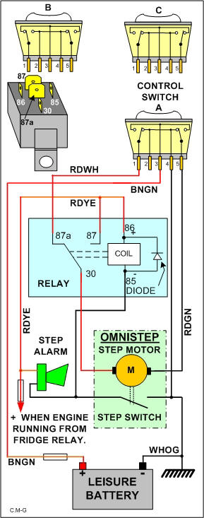
Just for info. Omnistore Electric Step.

wiring drawing .. and fault finding


img3.jpg


The control switch is a DOUBLE CHANGE OVER SWITCH. (Not a double pole change over as this is subtly different) This switch contains two change over switches, one switch changes over when the rocker is operated in one direction and the other switch changes over when the rocker is operated in the other direction. So it carries out a few more functions than just a simple ON/OFF switch.

The Omnistep has a permanent magnet motor. This means that if you reverse the polarity the motor will run in the opposite direction. The switch is designed to do this. The motor rotates in one direction to extend and the other direction to retract.

Nominally 5 amps is the expected working current for the motor. If however you keep your finger on the switch after the step has fully extended or retracted then the motor will stall. Under this condition the current will increase to a significantly higher figure. Sometimes referred to as the “blocking current”.

The Omnistep has two electrical components, the motor which moves the step and a switch that is OPEN only when the step is fully retracted. At all other times the switch will be closed.

Firstly the system is designed to retract the step and sound the alarm should you start your engine with the step extended.

Under this condition the control switch is as shown in switch picture A. Battery negative is connected to terminal 4 of the switch and comes back out of the switch at terminal 5. It is connected to the right hand end of the motor with a RDGN wire.

When the engine is running the FRIDGE relay is energised from the vehicle alternator D+ terminal. The fridge relay applies 12 volts to both the fridge and also the step relay terminal 86 (coil+) and one side of the alarm.

If the step is extended then the step switch will be closed. This will provide a negative supply to the alarm causing it to sound, and also the other end of the relay coil (85) causing it to energise.. Now that the relay is energised the fridge supply which is also connected to the relay terminal 87 is routed by the closed contacts to relay terminal 30 and provides a positive supply to the Omnistep motor. The motor will rotate causing the step to retract. When fully retracted the step switch will open, the relay will release, the alarm will go silent.

With the engine turned OFF the rocker switch can be depressed causing the step to extend.

Under this condition the control switch is as shown in switch picture C. Battery negative is connected to terminal 4 of the switch and comes back out of the switch at terminal 1. It is connected to the relay terminal 87a (normally closed contact) and comes out of the relay at terminal 30. From here it is routed to the left hand end of the motor.

A positive supply from the leisure battery enters the switch at terminal 3 via a BNGN wire. This positive supply leaves the switch at terminal 5 which is routed via a RDGN wire to the right hand end of the motor causing the step to extend. When the step has extended you must leave go of the switch or the current will increase to 14 amps!

With the engine turned OFF the rocker switch can be depressed causing the step to retract.

Under this condition the control switch is as shown in switch picture B. Battery negative is connected to terminal 4 of the switch and comes back out of the switch at terminal 5. It is routed to the right hand end of the motor.

A positive supply from the leisure battery enters the switch at terminal 3 via a BNGN wire. This positive supply leaves the switch at terminal 1. It is connected to the relay terminal 87a (normally closed contact) and comes out of the relay at terminal 30. From here it is routed to the left hand end of the motor causing the step to retract. When the step has retracted you must leave go of the switch or the current will increase to about 14 amps


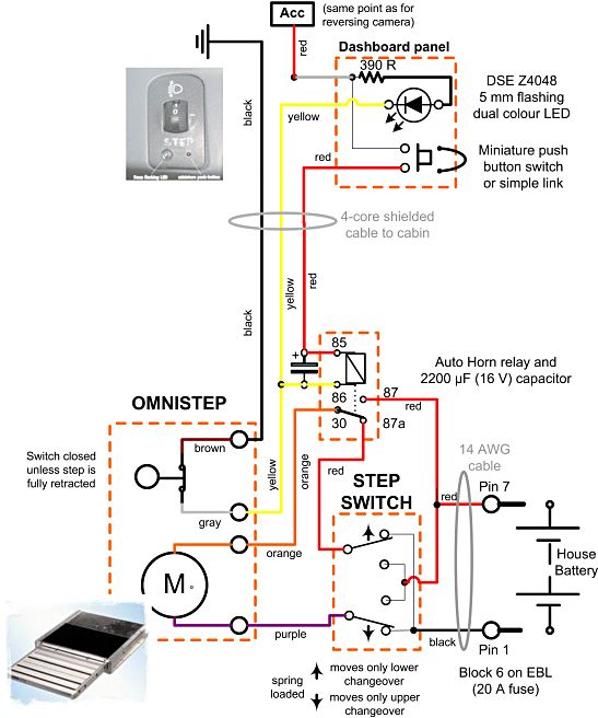
and another drawing


step_schematic.jpg
 
OP
OP
PCD

PCD

Free Member
Feb 2, 2016
4
0
Oldham
Funster No
41,547
MH
Hymer b534
Exp
Since 2015
Thanks to the brilliant replies,I just wounded if I had a factory fitted dash mounted switch would it lower the step as well as raise it?.
The cables on my switch by the door are only brown or blue,and did anyone fit an extra switch at the dash just think it's a worth while upgrade along with a warning light in place of the buzzer.
 

Join us or log in to post a reply.

To join in you must be a member of MotorhomeFun

Join MotorhomeFun

Join us, it quick and easy!

Log in

Already a member? Log in here.

Latest journal entries

Funsters who are viewing this thread

Back
Top