Central locking locking automatically, what a stupid idea! How do you wire in a fix?

Joined
Sep 9, 2019
Posts
1,349
Likes collected
3,005
Location
Runcorn
Funster No
63,956
MH
Swift Escape 640
Exp
Since Sept 2019
I guess that everybody on here that's got a relatively new Fiat Ducato based vehicle has come across the problem of the blasted vehicle locking itself unless you open the passenger door and the hab door momentarily after getting out of it. For those that don't know, if you don't do this really irritating procedure then the central locking locks you out.... even if your keys are still in the van! I've come across a "fix" that involves the vehicle's "converter socket" that's located behind the driver's seat at the bottom of the B post. Apparently you have to wire in a N. O. switch to ground at connection 6 (N. O. Normally Open) I'm not and never will be an auto spark but I'm willing to have a go at this. Do any of you know what I have to physically do? Can you point me in the direction of a suitable N. O. switch? And a wiring diagram with really easy to follow instructions?
I eagerly await your input, as, I suspect, do lots of others of us!

Cheers!

Russ
 
Okay, I have my PVC auto lock switched off and it neither auto locks when the sliding door is opened or when I drive off. Which suits me fine.
I like it for the security aspect so I know all doors are locked to save any chancer trying to get in when stopped.
 
Upvote 0
I believe I have the definitive answer for the autolock central locking operating when the vehicle is stationary, the keys are out of the ignition and you have just stepped out of the van but not opened either the Hab or the Passenger Cab door, or only opened one but not both of them.

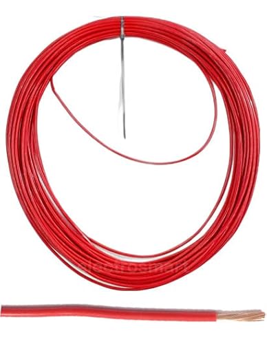
I am going to have wired by a tame autospark (who I have still to find as I write this, but investigations are ongoing...) a normally open (N.O.) magnetic switch (see among the items below) to the hab door frame, and it's actuator, a magnet, to the hinge side of the door. The N.O. switch has two wires coming from it, one needs to be attached to an earthing point on the chassis of the vehicle, the other one needs to be extended and routed either inside the van neatly all around the internal furniture/structures within the hab and cab spaces, or externally attached under the van in suitable corrugated plastic protective conduit, using zip ties or similar, and reappear at what is known as the BCM, Body Control Module. The BCM is located on UK spec vehicles behind a panel adjacent to the driver's right knee in the dashboard structure. I don't know where it will be on Hymer type vehicles I'm afraid! The wire needs to be connected to pole/pin 6 on the BCM. I have included a "repair wire kit" in my list of components as I believe that making off the connections to an additional pin is a real PITA!

The rational is that the BCM is tricked into thinking that the Hab door is open and doesn't start the countdown sequence to relock the van. The central locking and alarm functions will not be compromised. I will post my interrogation of the internet in the next post for those who want to have a more detailed explanation of the process.

Hope this furthers our collective knowledge on this issue.

The MoHo is going back to Spinney on Friday for them to have a third go at fixing the engine management warning light/DPF problem (see posts on warranty work elsewhere on MHF). I think I might ask them to install my fix while they have the van in bits and they are grubbing about under the dashboard hunting for the OBD11 reader socket.

Cheers!

Russ

 
This site contains affiliate links for which MHF may be compensated.
Upvote 0
These are the results of my research this morning, hope it helps! I had initially asked how to insert a diode into the system but you will see that this solution may have other, unacceptable, compromises.

Courtesy of Google and AI......


"To stop your Swift Escape 640 central locking system from auto-relocking itself after you unlock the vehicle and enter through the habitation door, it helps to understand why this occurs.
Why the Auto-Locking Happens
Your Swift motorhome is built on a Fiat Ducato base vehicle chassis. The central locking system is managed by Fiat’s Body Control Module (BCM). When you press the unlock button on the key fob, the BCM starts a 30-to-60-second countdown. If it does not detect a "door open" signal from one of the factory cab doors within that window, it assumes the unlock button was pressed by accident and automatically re-locks all doors for security. [1, 2, 3]
Because the Hartal habitation door lock is an addition by the motorhome builder (Swift) and its manual open/close mechanism is usually not wired back into the Fiat CAN bus or cab door lighting circuits, opening the habitation door does not reset the BCM's countdown. [1]

The Diode Workaround (How it Works)
Some owners use an inline electronic diode to bypass this problem, but it comes with a major compromise:[1]
The Hartal central locking actuator operates on a reverse polarity 2-wire system. To unlock, current flows down Wire A and returns via Wire B. To lock, the polarity reverses: current flows down Wire B and returns via Wire A. [1, 2]
If you cut one of these wires and splice in a standard diode (such as a 1N4007 or a heavier-duty 1N5408 3A diode), the diode acts as a one-way electrical valve.
  • It can be oriented to allow the unlock pulse to pass through normally.
  • When the van tries to send the lock pulse (including the automatic re-lock command), the reversed current is blocked by the diode, meaning the habitation door actuator cannot move to the locked position. [1]
⚠️ The Catch: This does not stop the cab doors from auto-locking; it only protects the habitation door from locking you out. Furthermore, because the diode permanently blocks the lock signal path, the key fob will no longer be able to lock the habitation door automatically. Every time you leave or lock the van, you will have to manually lock the habitation door using your physical key. [1]
How to wire it if you choose this route:
  1. Locate the two primary control wires going to the lock actuator (commonly routed through the plastic plunger contacts or flexible conduit at the base of the door). [1, 2]
  2. Use a 12V test light or multimeter across the two wires while someone presses the key fob buttons. Note which wire becomes positive (+12V) during the unlock cycle.
  3. Cut that specific wire.
  4. Solder or crimp the diode inline. The silver stripe (cathode) on the diode must point toward the door lock actuator side if it's placed on the positive feed side of the unlock stroke, allowing current to flow into the actuator to unlock it, but blocking the return ground path required when the polarity flips to lock.

Alternative (and Safer) Solutions
Instead of crippling your central locking loop with a diode, consider these cleaner workarounds:
  • The Free Habit: Train yourself to open a cab door (either driver or passenger) immediately after hitting the unlock button on the fob. Opening a cab door breaks the BCM's countdown cycle and stops the entire vehicle from auto-locking. [1]
  • The Microswitch Fix: The most robust technical solution is to install a standard Normally Open (N.O.) magnetic microswitch or mechanical pin switch to the habitation door frame. Wire this switch parallel into the passenger-side cab door switch wiring or to the designated side/rear door pin on the BCM socket (e.g., Pin 6 on modern Ducato modules). When the habitation door opens, it grounds the circuit, tricking the BCM into recognizing a door has opened, which natively aborts the auto-lock sequence. [1, 2]
If you would like to proceed with one of these options, let me know:
  • What year is your Swift Escape 640?
  • Do you prefer to try wiring a microswitch to save your cab locking functionality, or do you prefer the diode bypass despite losing remote locking?
AI responses may include mistakes. Learn more
  • Facebook·Bürstner Lyseo Gallery
    Has anyone worked out how to stop the habitation doors from ...
    I have also spoke to one of the engineers from the Burstner dealer. He said it's because the habitation door is not on the CAN bus...
  • Out & About Live
    Self Locking Doors - Motorhome Matters - Out & About Live
    If you are exiting by the habitation door then this is a design fault of many coachbuilt MH's with the hab door on the central loc...
  • The FIAT Forum
    New 2025 Ducato auto door locking
    Member The motorhome converter then wires in a N.O. to ground switch on the habitation door to pin 6 of this socket to provide a "
Show all
wiring a micro switch
Wiring a Normally Open (N.O.) magnetic microswitch or a mechanical pin switch is a much cleaner solution than using a diode. Instead of breaking your central locking function, this method tricks the Fiat Body Control Module (BCM) into recognizing that a door has opened, naturally resetting the auto-lock countdown timer. [1, 2]
Step 1: Choose Your Switch
  • Magnetic Reed Switch (Recommended): A two-piece magnetic contact switch (the type used in home burglar alarms) is ideal. One half goes on the frame and the other on the door. It requires no physical contact, will not wear out, and is completely hidden.
  • Mechanical Pin Switch: A standard automotive spring-loaded door plunger pin. This requires drilling a hole in the frame so the door physically depresses the pin when closed.
Note: For this circuit, you must buy a switch that is Normally Open (N.O.). When the door opens and the magnet moves away (or the pin pops out), the switch must close its internal contacts to connect your wire to the ground.

Step 2: Mount the Switch
  1. Attach the switch to the habitation door frame.
  2. Attach the corresponding magnet to the habitation door itself. Ensure that when the door is shut, the magnet sits directly next to the switch.

Step 3: Understand the Wiring Path
The Fiat Ducato BCM monitors doors by looking for a ground signal (0V). When a cab door opens, the factory switch closes, connecting a BCM sensing pin to the vehicle chassis (ground). [1]
You will wire your new switch to replicate this exact action.
  • Wire 1 from your microswitch: Connect this to a clean, metal part of the motorhome chassis (earth/ground).
  • Wire 2 from your microswitch: Run this wire forward into the cab to splice into the Fiat door-sensing circuit.

Step 4: Hook into the Fiat System
You have two choices for where to connect Wire 2:
Option A: Tap the Passenger Door Loom (Easiest DIY)
Instead of taking the dash apart, you can tap directly into the passenger cab door switch wiring.
  1. Locate the rubber boot or wiring loom passing from the passenger A-pillar into the passenger door, or find the interior light switch wire underneath the lower B-pillar trim.
  2. Locate the door status wire (typically a thin, colored wire that drops to 0V/ground when the passenger door opens).
  3. Use a scotch lock or solder your Wire 2 directly onto this wire.
  • Result: Opening the habitation door will trick the BCM into thinking the passenger door just opened. The interior cab lights will turn on briefly, and the auto-lock countdown will abort. [1]
Option B: Wire Directly to the BCM Pin 6 (The "Factory" Way)
If your Swift Escape uses a modern Ducato chassis base, Fiat actually leaves a dedicated slot vacant on the BCM specifically for motorhome builders to attach rear/side doors. [1]
  1. Locate the BCM (the main fuse board unit down by the driver’s right knee or under the lower dash panel).
  2. Locate the primary multi-pin connector plug.
  3. According to Fiat forum wiring layouts, Pin 6 on this designated socket acts as the "Side and rear door status signal" loop.
  4. Insert a proper terminal pin attached to Wire 2 into Pin 6. [1]
  • Result: The BCM will cleanly process the habitation door independently. It will instantly reset the auto-lock timer without turning on the front cab footwell lights or throwing a "Door Open" error on the dashboard while driving. [1]

Step 5: Test the Circuit
With the habitation door shut, unlock the motorhome using the key fob. Wait in the van without touching the cab doors. Open the habitation door. If wired correctly, you will hear a faint click or see the dash light acknowledge the action, and the 60-second countdown will permanently stop, leaving the van safely unlocked.
Would you like help identifying the exact wire colour for the passenger door loom on your specific model year, or do you need assistance locating Pin 6 on the BCM plug? [1]
AI responses may include mistakes. Learn more
  • The FIAT Forum
    New 2025 Ducato auto door locking
    Member The motorhome converter then wires in a N.O. to ground switch on the habitation door to pin 6 of this socket to provide a "
  • Facebook·Bürstner Lyseo Gallery
    Has anyone worked out how to stop the habitation doors from ...
    30 Oct 2025 — He said it's because the habitation door is not on the CAN bus of the van, so when you open the habitation door, it does not send ...
in step 4 action 2 above what colour is the door status wire and where exactly is it located on Fiat Ducato 2024 chassis
On the 2024 Fiat Ducato Series 9 chassis, Fiat handles the door triggers through the Body Control Module (BCM), which is located in the driver's side footwell behind the lower dash plastic panel. [1]
Depending on which method you choose from Step 4, here are the exact wire details:
1. Tapping the Cab Door Loom (Option A)
To access the passenger door switch signal without removing the door card, you need to tap into the loom as it enters the vehicle body at the passenger-side A-pillar (behind the plastic trim panel by the glove box/passenger footwell area).
  • The Wire Color: Pink with a Black stripe (coded as SN in Fiat factory eLearn technical diagrams).
  • The Location: Look for the multi-plug harness passing directly through the rubber boot from the passenger door. In the 2024 model, the microswitch inside the door latch assembly switches a clean negative earth ground over this wire when the door opens. [1]
2. Wiring Directly to the BCM (Option B - Highly Recommended)
For a 2024 model, rather than splicing into the passenger door wire, tapping the BCM cleanly maps the habitation door into the network.
  • The Connector Location: On the front of the BCM fuse board assembly (by the driver's right knee), locate the 60-pin blue connector plug (often labeled as Connector A or Plug A).
  • The Pin & Wire Color: Pin 6. If your Swift motorhome converter has not already used it, this pin slot will be blank/empty. If there is a wire already factory-populated in Pin 6, it will typically be a Green with a Yellow stripe or a Brown wire.
  • Action: You will need to crimp a mini-ISO female terminal pin to Wire 2 of your new habitation door microswitch, push it directly into Pin 6 of that blue plug, and snap the harness back into the BCM.
Safety Note: Always disconnect the vehicle's engine battery before unplugging connectors from the BCM to avoid triggering temporary airbag or CAN bus communication faults on your dashboard. [1]
Let me know if you need help finding the right terminal pins for the BCM plug, or if you'd like guidance on routing the wire safely from the habitation door to the cab!
AI responses may include mistakes. Learn more
  • YouTube
    Fiat Ducato Motorhome Van Blown Fuse location & Identification
    tonight we wanted to make a short video on the location of the Fiat Ducato fuse box and uh the position of it and uh where the fus...
  • Indie Campers
    Fiat Ducato – Dashboard warning lights guide
    It's important to know what car dashboard warning lights mean because you might be able to avoid a car breakdown or full-on failur...
  • The FIAT Forum
    Not another electric window problem! | FIAT Ducato (Gen 2)
    11 Mar 2021 — Written a review Here is a photo version of the elearn scematic, which may be better resolution than the pdf. The wire colours are...
i need help finding the right terminal pins for the BCM plug and guidance on routing the wire safely from the hab door to the cab
Here is the technical info on the terminal pins and practical guidance on routing your wire safely across the motorhome.
1. The Correct BCM Terminal Pin Type
The 60-pin blue connector housing on the 2024 Fiat Ducato BCM uses a highly specific, small automotive terminal: [1]
  • Terminal Name: Duotwin 0.64mm Female Terminal (specifically the Lance version, which has the locking barb/tang to secure it inside the plastic connector block). [1]
  • Alternatives / Search Terms: You can also search for TE Connectivity Micro Quadlok System (MQS) 0.64mm female terminals or Delphi/Aptiv MTS 0.64 unsealed female connector pins. They are identical in form factor and fit perfectly into the BCM slots. [1]
  • Pro-Tip: If you do not want to crimp microscopic pins yourself, search online for a "BCM Pre-Terminated Lead" or "MQS repair wire". These come with a 0.64mm female pin already factory-crimped onto a short length of wire, which you can simply solder or crimp directly onto the wire coming from your habitation door microswitch. [1, 2, 3]
  • How to Insert it: Use a small flathead screwdriver to gently release the colored secondary locking sliding tab on the blue BCM harness plug first. Slide your terminal pin into Pin slot 6 until you hear a distinct click, then push the locking slider back into place to secure all wires. [1]

2. Routing the Wire Safely (Habitation Door to Cab)
The goal is to route the wire invisibly and securely so it cannot get pinched, chaffed, or caught by moving parts.
Step A: Leaving the Habitation Door Frame
  1. Locate the existing flexible rubber conduit loop or the plastic spring-loaded plunger contact block at the hinge side/base of your Hartal door frame.
  2. If your door uses a flexible rubber conduit, fish your microswitch wire right through it alongside the central locking wires.
  3. If it uses spring contacts, do not use them for this switch—instead, run your microswitch wire directly out of the bottom of the stationary door frame, dropping it down underneath the motorhome's false floor or step well.
Step B: Navigating the Under-Floor Route
Because your Swift Escape 640 has a raised habitation floor (often containing underfloor water tanks or storage), you have two distinct paths forward:
  • The Interior Path (Safest/Easiest): Drop the wire into the step well trim or under the edge of the flooring. Route it forward along the vehicle side wall, threading it behind the lower galley/seating furniture bases. You will eventually bring it alongside the passenger or driver's side seat box.
  • The Exterior/Chassis Path (Alternative): If internal cabinetry blocks you, route the wire out through a sealed floor grommet into the under-chassis area. If you go under the van:
    • You must encase the wire in split-conduit (corrugated plastic tubing) to protect it from road debris and moisture.
    • Zip-tie it securely along existing brake lines or factory wiring looms—never zip-tie it to moving suspension components, handbrake cables, or hot exhaust pipes.
    • Bring it back up into the cab by drilling or pushing through one of the factory rubber wiring grommets located directly underneath the driver's or passenger's seat boxes.
Step C: Entering the Cab to the BCM
  1. Once your wire is inside the front cab area (near the seat boxes), tuck it neatly underneath the factory rubber floor mat or plastic cab door sill steps.
  2. Route it all the way forward toward the dashboard.
  3. Feed it up behind the lower steering column/pedal box plastic trim straight into the driver's side lower fuse box well, where the blue BCM connector plug sits waiting for Pin 6. [1, 2]
Next Steps
If you'd like to make sure you have everything ready before dismantling the dash, let me know:
  • Do you have an automotive crimping tool for small terminals, or would you prefer a link to pre-terminated "repair wires"?
  • Do you plan to route the wire internally through the furniture or externally under the chassis?
AI responses may include mistakes. Learn more
  • The FIAT Forum
    BCM pin connector? | FIAT Motorhomes / Campervans
    New member * ZaphodB said: I must admit I guessed at the 0.64 size, it could be the 1.5 size , it's just the tab width (in mm) - j...
  • YouTube·Phil Gamboa
    BCM Pre-Terminated Leads / Pinning your BCM
    1 Mar 2021 — BCM Pre-Terminated Leads / Pinning your BCM hello everyone it is Phil the harness doctor and in today's video I'm going to be show...
    31s
  • YouTube
    How To: Take Apart Your Ducato, Boxer or Relay Dashboard ...
    um the one nearest where you would normally put the key that faces the sky. again same screwdriver it's the T 25. and then one tha...
Show all
give me a link for pre-terminated “repair wires”. show me options for internally through the furniture and externally under the chassis
For the 2024 Fiat Ducato Series 9 BCM, you need standard 0.64mm MQS (Micro Quadlok System) female pins. Because the pins themselves are tiny and notoriously frustrating to crimp without specialized tools, using a pre-terminated "repair wire" (a length of wire with the pin already factory-crimped onto the end) makes the job much easier. [1]
1. Pre-Terminated Repair Wires
You can purchase the raw MQS terminals from RS UK if you want to crimp them yourself. However, the cleanest pre-assembled route is to look at carsystems.eu MQS Female Repair Cables. Alternatively, standard Volkswagen/Audi groups share this exact terminal style; you can source a Kazura MQS 000979133E Repair Wire from Amazon UK, which slots directly into the Fiat BCM plug housing. [1, 2, 3]
Once you click this into Pin 6, you will simply solder or crimp your extension wire onto the other end.

2. Wiring Path: Internal Through the Furniture
Routing the wire internally keeps it entirely protected from weather and road dirt. Because your Swift Escape 640 has a side-facing kitchen or lounge layout depending on the exact interior configuration, this is the most common path:
  • Pros: Complete protection from elements; no drilling through the external floor.
  • The Route:
    1. Drop the microswitch wire straight down the inside of the habitation door frame into the lower step well or internal floor edge.
    2. Run the wire horizontally along the base of the furniture (behind the kickboards, under the kitchen units, or through the bottom of the seating bed boxes).
    3. Bring the wire forward until you reach the rear of the driver's or passenger's cab seat box.
    4. Tuck the wire beneath the edge of the factory cab rubber floor mat or underneath the plastic side sill steps, routing it straight up behind the pedals into the lower dash fuse box where the BCM is mounted.
  • What to use: Use standard thin-wall automotive cable (0.5mm² to 0.75mm² is plenty for a basic ground switch signal) and wrap it in fabric cloth wiring tape to prevent rattles against the wooden furniture panels.

3. Wiring Path: External Under the Chassis
If your Swift’s internal cabinetry is completely sealed or blocked by appliances (like a low-mounted fridge or oven), going under the chassis is often much faster.
  • Pros: Bypasses tightly packed internal furniture and appliances.
  • The Route:
    1. Route the microswitch wire out from the door frame and drill a small hole straight down through the wooden habitation floor (usually hidden inside the door step well plastic trim or a nearby locker).
    2. Pull the wire all the way through underneath the van. Seal the drill hole completely with exterior-grade polyurethane sealant (like Sikaflex) to keep out moisture and road spray.
    3. Run the wire along the metal chassis rails, using heavy-duty zip ties to anchor it next to the thick factory brake lines or main chassis wiring looms. Stay far away from the exhaust pipe or moving suspension arms.
    4. Bring the wire back up into the cab by threading it through one of the factory rubber floor grommets located directly underneath the driver's seat box or passenger seat box. From there, run it under the cab floor mat directly into the BCM.
  • What to use: You must protect the wire from road salt, stones, and water. Encased the automotive wire inside a length of plastic split-conduit (corrugated tubing) for its entire run underneath the chassis.

Would you like advice on the best type of external sealant for the floor hole, or do you need tips on how to remove the plastic cab door sill steps to hide the wire neatly?
AI responses may include mistakes. Learn more
  • Google
    Kazura Repair Wire with Connector Terminal for Audi, Seat, Skoda and VW
    WHAT IT IS: A prewired repair wire with connector terminal, used to repair or extend a damaged wiring connection in the loom. VEHI...
  • Google
    TE Connectivity MQS Female
    TE Connectivity, MQS Female Receptacle Crimp (10), Product Type: Automotive Connector Terminal, Contact Plating: Gold, Minimum Ope...
  • Google
    Repair cable MQS Female with 2 pin contact
    Repair cable MQS Female with 2 PIN contact at both ends for SEAT. At Car-Systems.
show me a diagram of the precise location and layout of the Fiat Ducato 2024 BCM
1. BCM Location (Where to find it)
The Body Control Module (BCM) on the 2024 Fiat Ducato Series 9 is integrated directly behind the driver's side interior fuse box panel. [1, 2]
[=== DASHBOARD ===]
O (Steering Wheel)

[Pedals] [Lower Plastic Dash Trim]
└─► Remove 2x T25 Torx Screws
│
└──► [FUSE BOX & BCM] ◄── (Right knee area)
To expose the module:
  1. Locate the plastic storage pocket panel down by your right knee while sitting in the driver's seat.
  2. Use a T25 Torx screwdriver to remove the two securing screws (one facing the sky near the key column, one facing the driver's door).
  3. Pull the plastic cover firmly straight back to release the clips. The fuse board and BCM computer will be sitting directly exposed. [1, 2]

2. Connector Layout (Looking at the Face of the Unit)
When looking straight at the exposed board, you are looking at the combined Junction Unit (B002) and BCM (M001). The main wiring plugs sit vertically along the bottom edge below the blade fuses: [1, 2]
+--------------------------------------------+

| [ FUSES ] |
| [ FUSES ] |
+--------------------------------------------+

| |
| [CONN C] [ OBD ] [CONN A] |
| (Grey/Black) (Diagnostic (BLUE PLUG) |
| Port) (60-Pin) |
+--------------------------------------------+
│
└───► THIS IS YOUR TARGET
  • Connector C (Left side): Usually grey or black, controlling lighting and wiper functions.
  • OBD Port (Center): The trapezoid-shaped 16-pin diagnostic socket where mechanics plug in scanners.
  • Connector A (Right side): The 60-pin Blue Connector. This is where the door-sensing logic loops reside. [1, 2, 3, 4, 5]

3. Pin Layout for the 60-Pin Blue Connector (Connector A)
Unplug the blue harness by flipping down the black plastic latching bar. When looking directly at the mating face of the blue plastic female plug (where the pins slide in), it is divided into three rows of 20 pins: [1]
[ Top Latching Lever Clip ]
Row 1: [ 1] [ 2] [ 3] [ 4] [ 5] [*6*] [ 7] ... [20]
Row 2: [21] [22] [23] [24] [25] [26] [27] ... [40]
Row 3: [41] [42] [43] [44] [45] [46] [47] ... [60]
  • Pin 1 is typically located at the top-left corner of the grid.
  • Pin 6 (Target): Count six slots over from the top-left corner.
  • Identification Note: On modern Fiat connectors, you will see tiny numbers moulded into the plastic housing at the beginning and end of each row (e.g., 1, 20, 21, 40) to help you orient yourself. [1]
If your Swift motorhome converter left it completely stock, Slot 6 will be a blank, empty plastic hole. You will insert your pre-terminated Micro Quadlok System (MQS) repair pin straight into this slot until it clicks. [1]
What type of microswitch (magnetic or mechanical plunger) did you choose for the door frame? I can help clarify its terminal connections if needed.
AI responses may include mistakes. Learn more
  • YouTube
    How To: Take Apart Your Ducato, Boxer or Relay Dashboard ...
    um the one nearest where you would normally put the key that faces the sky. again same screwdriver it's the T 25. and then one tha...
  • Scribd
    BCM Wiring Diagrams and Pinouts | PDF | Switch
    BCM Wiring Diagrams and Pinouts The document provides connector and terminal part information for 7 body control module connectors...
  • Scribd
    BCM Connector Pinout and Wiring Guide | PDF | Headlamp
    BCM Connector Pinout and Wiring Guide This document provides wiring information for various connectors on a vehicle. It lists the ...
Show all
 
Upvote 0
Lenny could I use a diode instead of a switch as per your post attached?
Sorry I don't really know the answer to that one.
Your has 4 wire Solenoid mine is a two wire solenoid that is pulsed, short 12v pulse the solenoid goes one and the next pulse it goes the other way so I don't think it would work on mine.
 
Upvote 0
These are the results of my research this morning, hope it helps! I had initially asked how to insert a diode into the system but you will see that this solution may have other, unacceptable, compromises.

Courtesy of Google and AI......


"To stop your Swift Escape 640 central locking system from auto-relocking itself after you unlock the vehicle and enter through the habitation door, it helps to understand why this occurs.
Why the Auto-Locking Happens
Your Swift motorhome is built on a Fiat Ducato base vehicle chassis. The central locking system is managed by Fiat’s Body Control Module (BCM). When you press the unlock button on the key fob, the BCM starts a 30-to-60-second countdown. If it does not detect a "door open" signal from one of the factory cab doors within that window, it assumes the unlock button was pressed by accident and automatically re-locks all doors for security. [1, 2, 3]
Because the Hartal habitation door lock is an addition by the motorhome builder (Swift) and its manual open/close mechanism is usually not wired back into the Fiat CAN bus or cab door lighting circuits, opening the habitation door does not reset the BCM's countdown. [1]

The Diode Workaround (How it Works)
Some owners use an inline electronic diode to bypass this problem, but it comes with a major compromise:[1]
The Hartal central locking actuator operates on a reverse polarity 2-wire system. To unlock, current flows down Wire A and returns via Wire B. To lock, the polarity reverses: current flows down Wire B and returns via Wire A. [1, 2]
If you cut one of these wires and splice in a standard diode (such as a 1N4007 or a heavier-duty 1N5408 3A diode), the diode acts as a one-way electrical valve.
  • It can be oriented to allow the unlock pulse to pass through normally.
  • When the van tries to send the lock pulse (including the automatic re-lock command), the reversed current is blocked by the diode, meaning the habitation door actuator cannot move to the locked position. [1]
⚠️ The Catch: This does not stop the cab doors from auto-locking; it only protects the habitation door from locking you out. Furthermore, because the diode permanently blocks the lock signal path, the key fob will no longer be able to lock the habitation door automatically. Every time you leave or lock the van, you will have to manually lock the habitation door using your physical key. [1]
How to wire it if you choose this route:
  1. Locate the two primary control wires going to the lock actuator (commonly routed through the plastic plunger contacts or flexible conduit at the base of the door). [1, 2]
  2. Use a 12V test light or multimeter across the two wires while someone presses the key fob buttons. Note which wire becomes positive (+12V) during the unlock cycle.
  3. Cut that specific wire.
  4. Solder or crimp the diode inline. The silver stripe (cathode) on the diode must point toward the door lock actuator side if it's placed on the positive feed side of the unlock stroke, allowing current to flow into the actuator to unlock it, but blocking the return ground path required when the polarity flips to lock.

Alternative (and Safer) Solutions
Instead of crippling your central locking loop with a diode, consider these cleaner workarounds:
  • The Free Habit: Train yourself to open a cab door (either driver or passenger) immediately after hitting the unlock button on the fob. Opening a cab door breaks the BCM's countdown cycle and stops the entire vehicle from auto-locking. [1]
  • The Microswitch Fix: The most robust technical solution is to install a standard Normally Open (N.O.) magnetic microswitch or mechanical pin switch to the habitation door frame. Wire this switch parallel into the passenger-side cab door switch wiring or to the designated side/rear door pin on the BCM socket (e.g., Pin 6 on modern Ducato modules). When the habitation door opens, it grounds the circuit, tricking the BCM into recognizing a door has opened, which natively aborts the auto-lock sequence. [1, 2]
If you would like to proceed with one of these options, let me know:
  • What year is your Swift Escape 640?
  • Do you prefer to try wiring a microswitch to save your cab locking functionality, or do you prefer the diode bypass despite losing remote locking?
AI responses may include mistakes. Learn more
  • Facebook·Bürstner Lyseo Gallery
    Has anyone worked out how to stop the habitation doors from ...
    I have also spoke to one of the engineers from the Burstner dealer. He said it's because the habitation door is not on the CAN bus...
  • Out & About Live
    Self Locking Doors - Motorhome Matters - Out & About Live
    If you are exiting by the habitation door then this is a design fault of many coachbuilt MH's with the hab door on the central loc...
  • The FIAT Forum
    New 2025 Ducato auto door locking
    Member The motorhome converter then wires in a N.O. to ground switch on the habitation door to pin 6 of this socket to provide a "
Show all
wiring a micro switch
Wiring a Normally Open (N.O.) magnetic microswitch or a mechanical pin switch is a much cleaner solution than using a diode. Instead of breaking your central locking function, this method tricks the Fiat Body Control Module (BCM) into recognizing that a door has opened, naturally resetting the auto-lock countdown timer. [1, 2]
Step 1: Choose Your Switch
  • Magnetic Reed Switch (Recommended): A two-piece magnetic contact switch (the type used in home burglar alarms) is ideal. One half goes on the frame and the other on the door. It requires no physical contact, will not wear out, and is completely hidden.
  • Mechanical Pin Switch: A standard automotive spring-loaded door plunger pin. This requires drilling a hole in the frame so the door physically depresses the pin when closed.
Note: For this circuit, you must buy a switch that is Normally Open (N.O.). When the door opens and the magnet moves away (or the pin pops out), the switch must close its internal contacts to connect your wire to the ground.

Step 2: Mount the Switch
  1. Attach the switch to the habitation door frame.
  2. Attach the corresponding magnet to the habitation door itself. Ensure that when the door is shut, the magnet sits directly next to the switch.

Step 3: Understand the Wiring Path
The Fiat Ducato BCM monitors doors by looking for a ground signal (0V). When a cab door opens, the factory switch closes, connecting a BCM sensing pin to the vehicle chassis (ground). [1]
You will wire your new switch to replicate this exact action.
  • Wire 1 from your microswitch: Connect this to a clean, metal part of the motorhome chassis (earth/ground).
  • Wire 2 from your microswitch: Run this wire forward into the cab to splice into the Fiat door-sensing circuit.

Step 4: Hook into the Fiat System
You have two choices for where to connect Wire 2:
Option A: Tap the Passenger Door Loom (Easiest DIY)
Instead of taking the dash apart, you can tap directly into the passenger cab door switch wiring.
  1. Locate the rubber boot or wiring loom passing from the passenger A-pillar into the passenger door, or find the interior light switch wire underneath the lower B-pillar trim.
  2. Locate the door status wire (typically a thin, colored wire that drops to 0V/ground when the passenger door opens).
  3. Use a scotch lock or solder your Wire 2 directly onto this wire.
  • Result: Opening the habitation door will trick the BCM into thinking the passenger door just opened. The interior cab lights will turn on briefly, and the auto-lock countdown will abort. [1]
Option B: Wire Directly to the BCM Pin 6 (The "Factory" Way)
If your Swift Escape uses a modern Ducato chassis base, Fiat actually leaves a dedicated slot vacant on the BCM specifically for motorhome builders to attach rear/side doors. [1]
  1. Locate the BCM (the main fuse board unit down by the driver’s right knee or under the lower dash panel).
  2. Locate the primary multi-pin connector plug.
  3. According to Fiat forum wiring layouts, Pin 6 on this designated socket acts as the "Side and rear door status signal" loop.
  4. Insert a proper terminal pin attached to Wire 2 into Pin 6. [1]
  • Result: The BCM will cleanly process the habitation door independently. It will instantly reset the auto-lock timer without turning on the front cab footwell lights or throwing a "Door Open" error on the dashboard while driving. [1]

Step 5: Test the Circuit
With the habitation door shut, unlock the motorhome using the key fob. Wait in the van without touching the cab doors. Open the habitation door. If wired correctly, you will hear a faint click or see the dash light acknowledge the action, and the 60-second countdown will permanently stop, leaving the van safely unlocked.
Would you like help identifying the exact wire colour for the passenger door loom on your specific model year, or do you need assistance locating Pin 6 on the BCM plug? [1]
AI responses may include mistakes. Learn more
  • The FIAT Forum
    New 2025 Ducato auto door locking
    Member The motorhome converter then wires in a N.O. to ground switch on the habitation door to pin 6 of this socket to provide a "
  • Facebook·Bürstner Lyseo Gallery
    Has anyone worked out how to stop the habitation doors from ...
    30 Oct 2025 — He said it's because the habitation door is not on the CAN bus of the van, so when you open the habitation door, it does not send ...
in step 4 action 2 above what colour is the door status wire and where exactly is it located on Fiat Ducato 2024 chassis
On the 2024 Fiat Ducato Series 9 chassis, Fiat handles the door triggers through the Body Control Module (BCM), which is located in the driver's side footwell behind the lower dash plastic panel. [1]
Depending on which method you choose from Step 4, here are the exact wire details:
1. Tapping the Cab Door Loom (Option A)
To access the passenger door switch signal without removing the door card, you need to tap into the loom as it enters the vehicle body at the passenger-side A-pillar (behind the plastic trim panel by the glove box/passenger footwell area).
  • The Wire Color: Pink with a Black stripe (coded as SN in Fiat factory eLearn technical diagrams).
  • The Location: Look for the multi-plug harness passing directly through the rubber boot from the passenger door. In the 2024 model, the microswitch inside the door latch assembly switches a clean negative earth ground over this wire when the door opens. [1]
2. Wiring Directly to the BCM (Option B - Highly Recommended)
For a 2024 model, rather than splicing into the passenger door wire, tapping the BCM cleanly maps the habitation door into the network.
  • The Connector Location: On the front of the BCM fuse board assembly (by the driver's right knee), locate the 60-pin blue connector plug (often labeled as Connector A or Plug A).
  • The Pin & Wire Color: Pin 6. If your Swift motorhome converter has not already used it, this pin slot will be blank/empty. If there is a wire already factory-populated in Pin 6, it will typically be a Green with a Yellow stripe or a Brown wire.
  • Action: You will need to crimp a mini-ISO female terminal pin to Wire 2 of your new habitation door microswitch, push it directly into Pin 6 of that blue plug, and snap the harness back into the BCM.
Safety Note: Always disconnect the vehicle's engine battery before unplugging connectors from the BCM to avoid triggering temporary airbag or CAN bus communication faults on your dashboard. [1]
Let me know if you need help finding the right terminal pins for the BCM plug, or if you'd like guidance on routing the wire safely from the habitation door to the cab!
AI responses may include mistakes. Learn more
  • YouTube
    Fiat Ducato Motorhome Van Blown Fuse location & Identification
    tonight we wanted to make a short video on the location of the Fiat Ducato fuse box and uh the position of it and uh where the fus...
  • Indie Campers
    Fiat Ducato – Dashboard warning lights guide
    It's important to know what car dashboard warning lights mean because you might be able to avoid a car breakdown or full-on failur...
  • The FIAT Forum
    Not another electric window problem! | FIAT Ducato (Gen 2)
    11 Mar 2021 — Written a review Here is a photo version of the elearn scematic, which may be better resolution than the pdf. The wire colours are...
i need help finding the right terminal pins for the BCM plug and guidance on routing the wire safely from the hab door to the cab
Here is the technical info on the terminal pins and practical guidance on routing your wire safely across the motorhome.
1. The Correct BCM Terminal Pin Type
The 60-pin blue connector housing on the 2024 Fiat Ducato BCM uses a highly specific, small automotive terminal: [1]
  • Terminal Name: Duotwin 0.64mm Female Terminal (specifically the Lance version, which has the locking barb/tang to secure it inside the plastic connector block). [1]
  • Alternatives / Search Terms: You can also search for TE Connectivity Micro Quadlok System (MQS) 0.64mm female terminals or Delphi/Aptiv MTS 0.64 unsealed female connector pins. They are identical in form factor and fit perfectly into the BCM slots. [1]
  • Pro-Tip: If you do not want to crimp microscopic pins yourself, search online for a "BCM Pre-Terminated Lead" or "MQS repair wire". These come with a 0.64mm female pin already factory-crimped onto a short length of wire, which you can simply solder or crimp directly onto the wire coming from your habitation door microswitch. [1, 2, 3]
  • How to Insert it: Use a small flathead screwdriver to gently release the colored secondary locking sliding tab on the blue BCM harness plug first. Slide your terminal pin into Pin slot 6 until you hear a distinct click, then push the locking slider back into place to secure all wires. [1]

2. Routing the Wire Safely (Habitation Door to Cab)
The goal is to route the wire invisibly and securely so it cannot get pinched, chaffed, or caught by moving parts.
Step A: Leaving the Habitation Door Frame
  1. Locate the existing flexible rubber conduit loop or the plastic spring-loaded plunger contact block at the hinge side/base of your Hartal door frame.
  2. If your door uses a flexible rubber conduit, fish your microswitch wire right through it alongside the central locking wires.
  3. If it uses spring contacts, do not use them for this switch—instead, run your microswitch wire directly out of the bottom of the stationary door frame, dropping it down underneath the motorhome's false floor or step well.
Step B: Navigating the Under-Floor Route
Because your Swift Escape 640 has a raised habitation floor (often containing underfloor water tanks or storage), you have two distinct paths forward:
  • The Interior Path (Safest/Easiest): Drop the wire into the step well trim or under the edge of the flooring. Route it forward along the vehicle side wall, threading it behind the lower galley/seating furniture bases. You will eventually bring it alongside the passenger or driver's side seat box.
  • The Exterior/Chassis Path (Alternative): If internal cabinetry blocks you, route the wire out through a sealed floor grommet into the under-chassis area. If you go under the van:
    • You must encase the wire in split-conduit (corrugated plastic tubing) to protect it from road debris and moisture.
    • Zip-tie it securely along existing brake lines or factory wiring looms—never zip-tie it to moving suspension components, handbrake cables, or hot exhaust pipes.
    • Bring it back up into the cab by drilling or pushing through one of the factory rubber wiring grommets located directly underneath the driver's or passenger's seat boxes.
Step C: Entering the Cab to the BCM
  1. Once your wire is inside the front cab area (near the seat boxes), tuck it neatly underneath the factory rubber floor mat or plastic cab door sill steps.
  2. Route it all the way forward toward the dashboard.
  3. Feed it up behind the lower steering column/pedal box plastic trim straight into the driver's side lower fuse box well, where the blue BCM connector plug sits waiting for Pin 6. [1, 2]
Next Steps
If you'd like to make sure you have everything ready before dismantling the dash, let me know:
  • Do you have an automotive crimping tool for small terminals, or would you prefer a link to pre-terminated "repair wires"?
  • Do you plan to route the wire internally through the furniture or externally under the chassis?
AI responses may include mistakes. Learn more
  • The FIAT Forum
    BCM pin connector? | FIAT Motorhomes / Campervans
    New member * ZaphodB said: I must admit I guessed at the 0.64 size, it could be the 1.5 size , it's just the tab width (in mm) - j...
  • YouTube·Phil Gamboa
    BCM Pre-Terminated Leads / Pinning your BCM
    1 Mar 2021 — BCM Pre-Terminated Leads / Pinning your BCM hello everyone it is Phil the harness doctor and in today's video I'm going to be show...
    31s
  • YouTube
    How To: Take Apart Your Ducato, Boxer or Relay Dashboard ...
    um the one nearest where you would normally put the key that faces the sky. again same screwdriver it's the T 25. and then one tha...
Show all
give me a link for pre-terminated “repair wires”. show me options for internally through the furniture and externally under the chassis
For the 2024 Fiat Ducato Series 9 BCM, you need standard 0.64mm MQS (Micro Quadlok System) female pins. Because the pins themselves are tiny and notoriously frustrating to crimp without specialized tools, using a pre-terminated "repair wire" (a length of wire with the pin already factory-crimped onto the end) makes the job much easier. [1]
1. Pre-Terminated Repair Wires
You can purchase the raw MQS terminals from RS UK if you want to crimp them yourself. However, the cleanest pre-assembled route is to look at carsystems.eu MQS Female Repair Cables. Alternatively, standard Volkswagen/Audi groups share this exact terminal style; you can source a Kazura MQS 000979133E Repair Wire from Amazon UK, which slots directly into the Fiat BCM plug housing. [1, 2, 3]
Once you click this into Pin 6, you will simply solder or crimp your extension wire onto the other end.

2. Wiring Path: Internal Through the Furniture
Routing the wire internally keeps it entirely protected from weather and road dirt. Because your Swift Escape 640 has a side-facing kitchen or lounge layout depending on the exact interior configuration, this is the most common path:
  • Pros: Complete protection from elements; no drilling through the external floor.
  • The Route:
    1. Drop the microswitch wire straight down the inside of the habitation door frame into the lower step well or internal floor edge.
    2. Run the wire horizontally along the base of the furniture (behind the kickboards, under the kitchen units, or through the bottom of the seating bed boxes).
    3. Bring the wire forward until you reach the rear of the driver's or passenger's cab seat box.
    4. Tuck the wire beneath the edge of the factory cab rubber floor mat or underneath the plastic side sill steps, routing it straight up behind the pedals into the lower dash fuse box where the BCM is mounted.
  • What to use: Use standard thin-wall automotive cable (0.5mm² to 0.75mm² is plenty for a basic ground switch signal) and wrap it in fabric cloth wiring tape to prevent rattles against the wooden furniture panels.

3. Wiring Path: External Under the Chassis
If your Swift’s internal cabinetry is completely sealed or blocked by appliances (like a low-mounted fridge or oven), going under the chassis is often much faster.
  • Pros: Bypasses tightly packed internal furniture and appliances.
  • The Route:
    1. Route the microswitch wire out from the door frame and drill a small hole straight down through the wooden habitation floor (usually hidden inside the door step well plastic trim or a nearby locker).
    2. Pull the wire all the way through underneath the van. Seal the drill hole completely with exterior-grade polyurethane sealant (like Sikaflex) to keep out moisture and road spray.
    3. Run the wire along the metal chassis rails, using heavy-duty zip ties to anchor it next to the thick factory brake lines or main chassis wiring looms. Stay far away from the exhaust pipe or moving suspension arms.
    4. Bring the wire back up into the cab by threading it through one of the factory rubber floor grommets located directly underneath the driver's seat box or passenger seat box. From there, run it under the cab floor mat directly into the BCM.
  • What to use: You must protect the wire from road salt, stones, and water. Encased the automotive wire inside a length of plastic split-conduit (corrugated tubing) for its entire run underneath the chassis.

Would you like advice on the best type of external sealant for the floor hole, or do you need tips on how to remove the plastic cab door sill steps to hide the wire neatly?
AI responses may include mistakes. Learn more
  • Google
    Kazura Repair Wire with Connector Terminal for Audi, Seat, Skoda and VW
    WHAT IT IS: A prewired repair wire with connector terminal, used to repair or extend a damaged wiring connection in the loom. VEHI...
  • Google
    TE Connectivity MQS Female
    TE Connectivity, MQS Female Receptacle Crimp (10), Product Type: Automotive Connector Terminal, Contact Plating: Gold, Minimum Ope...
  • Google
    Repair cable MQS Female with 2 pin contact
    Repair cable MQS Female with 2 PIN contact at both ends for SEAT. At Car-Systems.
show me a diagram of the precise location and layout of the Fiat Ducato 2024 BCM
1. BCM Location (Where to find it)
The Body Control Module (BCM) on the 2024 Fiat Ducato Series 9 is integrated directly behind the driver's side interior fuse box panel. [1, 2]
[=== DASHBOARD ===]
O (Steering Wheel)

[Pedals] [Lower Plastic Dash Trim]
└─► Remove 2x T25 Torx Screws
│
└──► [FUSE BOX & BCM] ◄── (Right knee area)
To expose the module:
  1. Locate the plastic storage pocket panel down by your right knee while sitting in the driver's seat.
  2. Use a T25 Torx screwdriver to remove the two securing screws (one facing the sky near the key column, one facing the driver's door).
  3. Pull the plastic cover firmly straight back to release the clips. The fuse board and BCM computer will be sitting directly exposed. [1, 2]

2. Connector Layout (Looking at the Face of the Unit)
When looking straight at the exposed board, you are looking at the combined Junction Unit (B002) and BCM (M001). The main wiring plugs sit vertically along the bottom edge below the blade fuses: [1, 2]
+--------------------------------------------+

| [ FUSES ] |
| [ FUSES ] |
+--------------------------------------------+

| |
| [CONN C] [ OBD ] [CONN A] |
| (Grey/Black) (Diagnostic (BLUE PLUG) |
| Port) (60-Pin) |
+--------------------------------------------+
│
└───► THIS IS YOUR TARGET
  • Connector C (Left side): Usually grey or black, controlling lighting and wiper functions.
  • OBD Port (Center): The trapezoid-shaped 16-pin diagnostic socket where mechanics plug in scanners.
  • Connector A (Right side): The 60-pin Blue Connector. This is where the door-sensing logic loops reside. [1, 2, 3, 4, 5]

3. Pin Layout for the 60-Pin Blue Connector (Connector A)
Unplug the blue harness by flipping down the black plastic latching bar. When looking directly at the mating face of the blue plastic female plug (where the pins slide in), it is divided into three rows of 20 pins: [1]
[ Top Latching Lever Clip ]
Row 1: [ 1] [ 2] [ 3] [ 4] [ 5] [*6*] [ 7] ... [20]
Row 2: [21] [22] [23] [24] [25] [26] [27] ... [40]
Row 3: [41] [42] [43] [44] [45] [46] [47] ... [60]
  • Pin 1 is typically located at the top-left corner of the grid.
  • Pin 6 (Target): Count six slots over from the top-left corner.
  • Identification Note: On modern Fiat connectors, you will see tiny numbers moulded into the plastic housing at the beginning and end of each row (e.g., 1, 20, 21, 40) to help you orient yourself. [1]
If your Swift motorhome converter left it completely stock, Slot 6 will be a blank, empty plastic hole. You will insert your pre-terminated Micro Quadlok System (MQS) repair pin straight into this slot until it clicks. [1]
What type of microswitch (magnetic or mechanical plunger) did you choose for the door frame? I can help clarify its terminal connections if needed.
AI responses may include mistakes. Learn more
  • YouTube
    How To: Take Apart Your Ducato, Boxer or Relay Dashboard ...
    um the one nearest where you would normally put the key that faces the sky. again same screwdriver it's the T 25. and then one tha...
  • Scribd
    BCM Wiring Diagrams and Pinouts | PDF | Switch
    BCM Wiring Diagrams and Pinouts The document provides connector and terminal part information for 7 body control module connectors...
  • Scribd
    BCM Connector Pinout and Wiring Guide | PDF | Headlamp
    BCM Connector Pinout and Wiring Guide This document provides wiring information for various connectors on a vehicle. It lists the ...
Show all
I've just finished war and peace so I'll start this now🤣🤣🤣🤣
 
Upvote 0
Hey MikeyT if I’ve found the answer to this and I find an outfit to do the mod for the right money I think this will be a license to print ££££
 
Upvote 0
I know this feed appears to be based on fiat based vehicles but I can’t help but wonder if this can be changed diagnostically via a specialist.

For example, our Ford based MH did not suffer directly from this auto relock issue as the hab door is wired in to the Ford OE system so sees the hab door open/close.

However almost from day one of ownership we have had intermittent hab door contact issue causing the hab door not to lock, cleaning the elements would always cure it for a while.

Recently we have had a few issues with the same contacts causing the relock issue as it occasionally due to contact issues fails to see the door was opened.

Because I was fed up with cleaning the already clean contacts constantly, I managed to change to BCMi coding via a specialist Ford diagnostic tool to switch off the auto relock function.

When I was chatting with my son who is a Ford master tech he confirmed that the Ford dealer tool cannot change the setting.

So dealer may not be able too but can fiat specialist or generic diag specialist companies change it on the fiats I wonder?
 
Upvote 0
Individual converters wire in all sorts of changes to the manufacturers’ systems. For instance, on newer Rapidos, when you come to a stop and open any door, the electric step automatically comes out and the hab door light comes on.

This was designed to be part of the “Welcome home” function, but the system activates even when you’ve been driving, then stop and get out! It’s a potential hazard in situations where you’ve had to park close to a wall or in a narrow space at a supermarket.

Rapido confirm that it is possible to override, but at extra cost. Bloody annoying when a “convenience” feature becomes an inconvenience, instead!

We’ve just had to train ourselves to anticipate the step popping out and adapt our parking accordingly, but I wish I knew how to override it myself…
 
Upvote 0
Not sure what Adria have done
Hi, I’m not on about central locking working when the keys are in the ignition and the van is moving. I’m on about when the van is stationary, the keys are out of the ignition, perhaps on the table in the lounge area, and you open, then close, the hab door. And you haven’t opened any other doors and the damned thing locks you out! I’ve already switched off the auto lock central locking when on the move. But thanks for your input!
On my new Adria, if I unlock the MH & open the hab door, the van will not autolock regardless of whether I open driver or passenger door so there must be a proper fix for it. It will autolock if I dont open any doors after unlocking.
 
Upvote 0
Not sure what Adria have done

On my new Adria, if I unlock the MH & open the hab door, the van will not autolock regardless of whether I open driver or passenger door so there must be a proper fix for it. It will autolock if I dont open any doors after unlocking.
I guess they have wired a door open switch on the hab door.
 
Upvote 0
Not sure what Adria have done

On my new Adria, if I unlock the MH & open the hab door, the van will not autolock regardless of whether I open driver or passenger door so there must be a proper fix for it. It will autolock if I dont open any doors after unlocking.
Howard I think your Adria has the mod either retro or factory fitted, just like Swift should have done to ours!!
 
Upvote 0
I've found a garage willing to do this mod for me, BBMF ltd. near Warrington. I think it will take two hours at £90/hour. I'll report back after its been done, appointment is 30th September.
 
Upvote 0
I know this feed appears to be based on fiat based vehicles but I can’t help but wonder if this can be changed diagnostically via a specialist.

For example, our Ford based MH did not suffer directly from this auto relock issue as the hab door is wired in to the Ford OE system so sees the hab door open/close.

However almost from day one of ownership we have had intermittent hab door contact issue causing the hab door not to lock, cleaning the elements would always cure it for a while.

Recently we have had a few issues with the same contacts causing the relock issue as it occasionally due to contact issues fails to see the door was opened.

Because I was fed up with cleaning the already clean contacts constantly, I managed to change to BCMi coding via a specialist Ford diagnostic tool to switch off the auto relock function.

When I was chatting with my son who is a Ford master tech he confirmed that the Ford dealer tool cannot change the setting.

So dealer may not be able too but can fiat specialist or generic diag specialist companies change it on the fiats I wonder?
MES lets you alter the alarm, immobilizer and central locking behaviour on older Ducatos by changing the country setting. Most used to be set to Netherlands a few years ago to turn off the internal motion sensors but things have probably moved on a lot since the simpler old days ☹️
 
Upvote 0
I must confess, I’m finding it difficult to understand that your keys are on the table and it locked you out! Surely you opened one door or another to put the keys there in the first place?
You need an ODB scanner to change/disable the auto lock feature. There are two settings:

1. Lock 45 seconds after unlocking and engine not started and all doors are shut.

2. Lock 30 seconds if key not detected near steering lock.

I use an ODBeleven scanner but I’m sure other scanner brands can expose these options.

The only annoying option I can’t disable is the single/brief horn sound when I lock the doors and a one of the doors are not fully closed. Especially annoying to campsite neighbours if I accidentally press the door lock button on my keyfob.
 
Upvote 0
Hi TGL, if this is indeed the case, why don't Motorhome manufacturers do it as a matter of course? Does this have to be done using a Fiat specific OBD reader? So far BBFM in Warrington have looked at the problem and are deciding whether an OBD “fix” or a physical wiring fix is the best way to go. If you have more info on the OBD fix could you post it here please? TIA!

Russ
 
Upvote 0

Join us or log in to post a reply.

To join in you must be a member of MotorhomeFun

Join MotorhomeFun

Join us, it quick and easy!

Log in

Already a member? Log in here.

Forum posts reflect the views of individual users and not MotorhomeFun.
MotorhomeFun does not endorse or verify user-generated content.

Back
Top