Leisure battery saga part 2 - help Jon! (1 Viewer)

kelpbeds

Free Member
Sep 16, 2011
100
12
shrewsbury
Funster No
18,194
MH
c class
Exp
since 2006
Follow on from 'leisure battery confusion' post.

It was all going well, got the relay in (after having found switched live) which worked perfectly and fired everything up (feeling very pleased at this point). The Sterling started okay so I checked how many amps it was delivering. Started at 14a, nice, then dropped to around 6a, not so good. I checked how much charge was in the starter battery (as the Sterling wouldn't give it power unless it needed it)and the BM1 battery condition meter said 75% so I figured the Sterling should be giving it more amps than that.
So I had a think.
1. I'm now on one 95ah battery (temporarily) whereas before I was on 2 x 115ah plus the auxillary battery i.e. 3 leisure batteries. Does this make a difference to how much the Sterling chucks out?
2. I also realised that I had only used 27amp wire to connect the Sterling to the leisure battery so I changed this for 110amp stuff and moved the Sterling back right next to the leisure batteries to eliminate length of wire and thickness. But the result was the same. Battery at 75%, fire up engine, Sterling whacks up to around 14amps then gradually goes down to 6amps.
I've also checked that the BM1 is setup correctly i.e. I have told it that the battery is 95ah, so it is correct when it reads 75% charge. Oh and I took out the relay to try it with this in and without, but didn't make any difference.

I am hoping this is just because I have changed from 3 batteries to 1 but I'm not sure. Before when the 3 batteries were at 75% charge and with the engine ticking over, the Sterling would pump out a constant charge of around 14amps.

What's going on now!? Help Jon please! :Blush:

Thanks
Tim
 

jonandshell

Free Member
Dec 12, 2010
5,476
8,299
Norfolk
Funster No
14,648
MH
Not got one!
Exp
Since 2006
The only things I can think of are the following-

The leisure battery is close to charged already, therefore the Sterling is coming to the end of its charging cycle. The status LEDs on the Sterling will indicate where it's at. Current reduces as the battery approaches a full charge.

The solar charge regulator is supplying charging voltage and bumping up the leisure battery voltage. The Sterling again thinks the leisure battery is nearly charged.

Might be worth trying to disconnect the solar kit or try it in the dark!

If the Solar kit is causing the problem, it would be best to connect it to the main supply at the distribution panel, because when parked up, it will be then connected to the leisure battery. When you are driving, of course, the leisure battery will be disconnected from all but the Sterling.

Sorry, but it's the best I can come up with!!!
 
OP
OP
K

kelpbeds

Free Member
Sep 16, 2011
100
12
shrewsbury
Funster No
18,194
MH
c class
Exp
since 2006
Cheers Jon, I did try it in the dark, like an hour ago or so. And unless the battery monitor is lying it isn't approaching the end of the charging cycle. Plus I whacked the heater on for a while until the low voltage light came on to ensure that the battery voltage was down.
Might be worth giving Sterling a ring I reckon to see what they think. Will post and information I get from them.
Thanks
Tim

Subscribers  do not see these advertisements


jonandshell

Free Member
Dec 12, 2010
5,476
8,299
Norfolk
Funster No
14,648
MH
Not got one!
Exp
Since 2006
It might be worth that call, that 50 Amps might only be output into a bigger battery than you have fitted at the moment.

I have tested ours using a clamp ammeter in the past and we do get the full 50 amps when the batteries are nearly flat.

Those Sterling status LEDs do give the best indication of whats going on though. Ours always get to the 'float' charge after a bit of a run.
 
OP
OP
K

kelpbeds

Free Member
Sep 16, 2011
100
12
shrewsbury
Funster No
18,194
MH
c class
Exp
since 2006
Will give Sterling a ring today, to see what they have to say. 50amps sounds very impressive Jon, I can only dream of that!

Another clue is that the timing light (yellow) comes on on the Sterling, which might indicate that it thinks it is coming to the end of the charge.

And good idea re resetting BM1 freelanderuk, will give that a whirl.

Glad you are enjoying the thread Popeye, will def keep it all public. :Smile:
 

eddie

LIFE MEMBER
Oct 4, 2007
8,140
41,145
Taunton Somerset
Funster No
540
MH
RV
Exp
since 1989
What clamp meter do you have that works on DC please, as I have always been told they will only work on A/C

Most decent ones do, CPC or Radio Spares is a good source.

Essential for our guys in the workshops

Eddie

Subscribers  do not see these advertisements


eddie

LIFE MEMBER
Oct 4, 2007
8,140
41,145
Taunton Somerset
Funster No
540
MH
RV
Exp
since 1989
LOL I replied to this but lost it!

Have you put the output of the Sterling unit in series with the shunt on the BM1?

Have you upgraded the Negative connection to the chassis with cable the same or bigger than you have used to upgrade the Positive connection?

Have you connected the shunt so as one side connects to the Negative terminal of the battery and nothing else, and nothing else on the negative post of the battery and ALL other connections are on the "other" side of the BM1 shunt included the uprated Negative to Chassis connection!

Have fun! If your still stuck post a couple of picks and I will sort you out!

Eddie.
 

Jaws

LIFE MEMBER
Sep 26, 2008
23,827
72,271
Thetford Norfolk
Funster No
4,189
MH
C class, Chieftain
Exp
since 2006 ( I think ! )
The percentage is only a calculation twixt the amperage delivered and the battery voltage

Would it be possible to get an accurate voltage reading across the leisure battery ?

If it is about 13.8 v then it has already reached the gassing voltage so the rate of charge would drop dramatically..

The charger has NO idea what the capacity of the battery is it is charging, only what voltage it is sitting at.. and all its calculations are based on that one bit of info
 
OP
OP
K

kelpbeds

Free Member
Sep 16, 2011
100
12
shrewsbury
Funster No
18,194
MH
c class
Exp
since 2006
Thanks for replies.

Eddie.

1. Have you put the output of the Sterling unit in series with the shunt on the BM1? - Err, not sure -will get some pics, basically output of sterling is now directly on pos terminal of leisure battery, shunt is connected directly to leisure battery as per set up instructions.

2.Have you upgraded the Negative connection to the chassis with cable the same or bigger than you have used to upgrade the Positive connection?
No and do you mean from the chassis to the neg of the leisure battery?

3.Have you connected the shunt so as one side connects to the Negative terminal of the battery and nothing else, and nothing else on the negative post of the battery and ALL other connections are on the "other" side of the BM1 shunt included the uprated Negative to Chassis connection!
Ah yes, I did manage to do that ok! (again will get pics sorted later)

Plus I spoke to Sterling today (think points from Jaws will be answered in this)
The guy asked me what the output from the Sterling was in volts. I duly measured it and it was 14.4 volts. So immediately he said that the Sterling was working fine. He then asked me to measure it at the leisure battery where it was 14.3 (or so if I remember correctly) so he pointed out there is a voltage drop (albeit slight I guess) due to poor cable etc..
I said that I was only getting a reading of 6amps or so on the BM1. He replied that the BM1 is a cheap pile of **** and because it works from the negative it can't really measure what the Sterling is pushing out and that I need a positive meter to measure it properly.
But he pointed out that that wasn't necessary and just to trust that the Sterling was doing it's job.
He also said that it was up to the battery as to how many amps it would take as the power was there from the Sterling.
Must admit he lost me a bit in technicalities but the general gist was that everything was fine apart from some voltage loss.
Interesting to see what everyone else makes of this. Will get some pics later after work.
Many thanks
Tim

Subscribers  do not see these advertisements


eddie

LIFE MEMBER
Oct 4, 2007
8,140
41,145
Taunton Somerset
Funster No
540
MH
RV
Exp
since 1989
Thanks for replies.

Eddie.

1. Have you put the output of the Sterling unit in series with the shunt on the BM1? - Err, not sure -will get some pics, basically output of sterling is now directly on pos terminal of leisure battery, shunt is connected directly to leisure battery as per set up instructions.

2.Have you upgraded the Negative connection to the chassis with cable the same or bigger than you have used to upgrade the Positive connection?
No and do you mean from the chassis to the neg of the leisure battery?

3.Have you connected the shunt so as one side connects to the Negative terminal of the battery and nothing else, and nothing else on the negative post of the battery and ALL other connections are on the "other" side of the BM1 shunt included the uprated Negative to Chassis connection!
Ah yes, I did manage to do that ok! (again will get pics sorted later)

Plus I spoke to Sterling today (think points from Jaws will be answered in this)
The guy asked me what the output from the Sterling was in volts. I duly measured it and it was 14.4 volts. So immediately he said that the Sterling was working fine. He then asked me to measure it at the leisure battery where it was 14.3 (or so if I remember correctly) so he pointed out there is a voltage drop (albeit slight I guess) due to poor cable etc..
I said that I was only getting a reading of 6amps or so on the BM1. He replied that the BM1 is a cheap pile of **** and because it works from the negative it can't really measure what the Sterling is pushing out and that I need a positive meter to measure it properly.
But he pointed out that that wasn't necessary and just to trust that the Sterling was doing it's job.
He also said that it was up to the battery as to how many amps it would take as the power was there from the Sterling.
Must admit he lost me a bit in technicalities but the general gist was that everything was fine apart from some voltage loss.
Interesting to see what everyone else makes of this. Will get some pics later after work.
Many thanks
Tim

Trust me Tim you don't need any more opinions. From his remarks you spoke to Charles, and he knows everything.

Let me see the pictures lol

If you don't uprate the ground your limiting the big cable to the capacity of the little cable! in simple terms!

Eddie
 

jonandshell

Free Member
Dec 12, 2010
5,476
8,299
Norfolk
Funster No
14,648
MH
Not got one!
Exp
Since 2006
Lots of info there Tim!!

Being a forklift technician myself, I tend to take some facts for granted. Being in a the trade I am so used to working with heavy duty DC amperages that I take the use of heavy cables and connections for granted! I have used 32 mm2 and 16mm2 cable with proper heavy duty lugs throughout for my cabling.
Maybe I should have pointed that out at the start! Sorry if I let you down on that point Tim.

The Sterling bloke is probably quite right about that volt drop if you are using cable more suited to wiring up a set of spotlights and yellow crimp connectors!

The yellow 'timed' light certainly means the battery is approaching full charge also!

Sounds like you need a bit of thicker cable and we will be there!!!!::bigsmile:
 
OP
OP
K

kelpbeds

Free Member
Sep 16, 2011
100
12
shrewsbury
Funster No
18,194
MH
c class
Exp
since 2006
Jon, I've got some 110amp cable on order with lugs to re do it. Should have figured out that myself really! And as you say, nearly there!

Shame the BM1 doesn't measure the amount of amps the Sterling is providing, it would be nice to know. But I guess the important thing is that the Sterling is doing it's job ok.

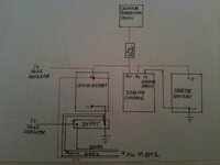
Eddie I have attached a circuit diagram which I drew, though that would be clearer than pics of the actual setup. This shows how the BM1 is connected and how everything else is set up. I presume the earth you mean that needs uprating is the one that is now on the shunt?

Oh and to Chris, I looked in manual of BM1 but couldn't see anything about resetting the whole unit. You can reset the ah and change a couple of other things in 'ENG' mode but not reset. Do you know something I don't?

Many thanks to all
Tim

Subscribers  do not see these advertisements


Attachments

  • circuit diagram van.jpg
    circuit diagram van.jpg
    98.4 KB · Views: 25
OP
OP
K

kelpbeds

Free Member
Sep 16, 2011
100
12
shrewsbury
Funster No
18,194
MH
c class
Exp
since 2006
Oh and for anyone who is searching for a switched live in their Transit. The one I found is behind the glove box (easily pulls away) and to the left there is a connector with about 20 wires going in. The orange one on the bottom is a switched live.
 

eddie

LIFE MEMBER
Oct 4, 2007
8,140
41,145
Taunton Somerset
Funster No
540
MH
RV
Exp
since 1989
Jon, I've got some 110amp cable on order with lugs to re do it. Should have figured out that myself really! And as you say, nearly there!

Shame the BM1 doesn't measure the amount of amps the Sterling is providing, it would be nice to know. But I guess the important thing is that the Sterling is doing it's job ok.

Eddie I have attached a circuit diagram which I drew, though that would be clearer than pics of the actual setup. This shows how the BM1 is connected and how everything else is set up. I presume the earth you mean that needs uprating is the one that is now on the shunt?

Oh and to Chris, I looked in manual of BM1 but couldn't see anything about resetting the whole unit. You can reset the ah and change a couple of other things in 'ENG' mode but not reset. Do you know something I don't?

Many thanks to all
Tim

There should be nothing connected to the Negative post except the shunt and nothing on the battery side of the shunt except the negative post. All other Negative connections should be on the "Other" side of the shunt, including a chassis connection at least the diameter of the "new" cable used for Positive from the Sterling unit

Eddie
 

jonandshell

Free Member
Dec 12, 2010
5,476
8,299
Norfolk
Funster No
14,648
MH
Not got one!
Exp
Since 2006
Oh and for anyone who is searching for a switched live in their Transit. The one I found is behind the glove box (easily pulls away) and to the left there is a connector with about 20 wires going in. The orange one on the bottom is a switched live.

I found one around there somewhere for the reversing camera!

The circuit diagram looks good to me Tim!
I am not familiar with the BM1 though, have never looked at one.

I am waiting for the comments about the missing split charge relay and cabling on the diagram though! lol Don't worry, I know they are there!

Looks like you've nailed it! Things will be even better once you get those Trojans!

It might be worth trying your new setup without the solar. We have never felt the need for any more than the traction batteries and Sterling. If you are pleased with the performance without the solar, you could flog the kit to help pay for the new Trojans!!!::bigsmile:

Subscribers  do not see these advertisements

 
OP
OP
K

kelpbeds

Free Member
Sep 16, 2011
100
12
shrewsbury
Funster No
18,194
MH
c class
Exp
since 2006
Hi Eddie,
Thanks for your input.
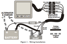
Just had a look at the BM1 manual and it suggests, nothing attached to negative on battery other than shunt connection and everything attached to other side of shunt as you said. But the diagram does show that the black and white wires should be connected to the same side of the shunt that the negative of the battery is connected to, as I have connected them to, no? (I will uprate the earth connection from the shunt)
I have attached diag from manual to show.
Cheers
Tim
 

Attachments

  • Picture 1.png
    Picture 1.png
    42.7 KB · Views: 17
OP
OP
K

kelpbeds

Free Member
Sep 16, 2011
100
12
shrewsbury
Funster No
18,194
MH
c class
Exp
since 2006
Yeah, sorry for any bits I missed Jon ;-), was sweating just drawing up what I managed! Trojans arrive tomorrow so looking forward to getting it all in properly.
Good point re solar, will see how it goes.
Cheers
Tim
 

eddie

LIFE MEMBER
Oct 4, 2007
8,140
41,145
Taunton Somerset
Funster No
540
MH
RV
Exp
since 1989
Hi Eddie,
Thanks for your input.
Just had a look at the BM1 manual and it suggests, nothing attached to negative on battery other than shunt connection and everything attached to other side of shunt as you said. But the diagram does show that the black and white wires should be connected to the same side of the shunt that the negative of the battery is connected to, as I have connected them to, no? (I will uprate the earth connection from the shunt)
I have attached diag from manual to show.
Cheers
Tim

LOL Yes the actual measuring wires across the shunt have to be connected. A good description of how a shunt works is here Link Removed

Uprating the Negative is vital yet so often missed!

Easy for us as we have installed more than most

Eddie

Subscribers  do not see these advertisements


pappajohn

LIFE MEMBER
Aug 26, 2007
43,286
49,202
Dark side of the moon
Funster No
172
Exp
Since 2005
What clamp meter do you have that works on DC please, as I have always been told they will only work on A/C


this is mine Roger......just a different name on it....mines an Acel.

[ame="http://www.amazon.co.uk/PCE-Instruments-PCE-DC3-Clamp-meter/dp/B001CNUM5C/ref=sr_1_61?ie=UTF8&qid=1325711837&sr=8-61"]clamp meter[/ame]


AC and DC

low range AC & DC 1ma to 2amps
high range AC & DC 1ma to 80amps
 

Join us or log in to post a reply.

To join in you must be a member of MotorhomeFun

Join MotorhomeFun

Join us, it quick and easy!

Log in

Already a member? Log in here.

Latest journal entries

Funsters who are viewing this thread

Back
Top