Homebrew solar tracker. (1 Viewer)

Feb 27, 2011
14,731
75,861
UK
Funster No
15,452
MH
Self Build
Exp
Since 2005
I did think about doing this some time ago. Even as a programmer for something this simple I was going to go for a simple op amp comparator along with a bunch of Light Dependent Resistors (LDR's). This would drive 2 stepper motors.

There would be a simple timer circuit something like a 555 timer triggered by the solar panel losing power. After 5 minutes of no power it would lie the panel flat.
After 5 minutes of gaining power again it would switch the tracking circuit on.

The tracking would be triggered every X minutes by another 555 circuit.

I am not sure if I still have my rough schematics somewhere, I may have binned them when I went full timing. The electronics if memory served would have cost around £25 excluding the motors.

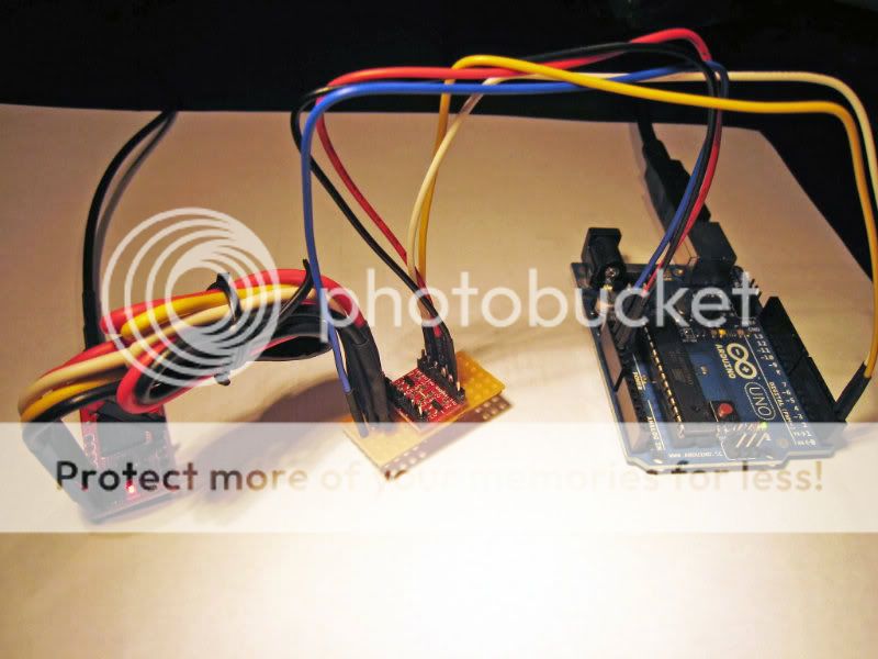
The arduino is a nice bit of kit but a bit too complex for a simple job like this. After you have added the extra shields and controllers it is cheaper to do it with discreet electronics.

If you definately want to go the microcontroller route then it may be worth looking at the Raspberry pi when it comes out. It's British and has some of the feel of the BBC micro about it but at $25 is dirt cheap.
http://www.raspberrypi.org/

Good luck with the project, its a fun one ::bigsmile:

PS: the 741 op amp chip and the 555 timer chip are less than £1.00 each.:thumb:
 

hilldweller

LIFE MEMBER
Dec 5, 2008
605
36,109
Macclesfield
Funster No
5,089
MH
Zilch Mk1
Exp
From Aug 2007
The arduino is a nice bit of kit but a bit too complex for a simple job like this.

Odd I'd have said it was too simple. On a job like this a display and keyboard can greatly ease development but this board is too limited to do this.

Doing it The Olde Way makes no sense in the 21st century.
 
Feb 27, 2011
14,731
75,861
UK
Funster No
15,452
MH
Self Build
Exp
Since 2005
Doing it The Olde Way makes no sense in the 21st century.

I work on the principle of KISS :winky: There is also the cost issue.

I would make the board, once tested and working bung it in a tub with some potting compound and it should work for decades....

My original trade was electronics tech, my current business is programming. I tend to pick what I feel will either get the job done quickly or be simple in the long run and always keep the TCO in mind.

With the arduino, I would be forever tempted to add extra features, such as GPS, Compass, lookup tables etc etc etc. The project would never be finished and would spend more time not working due to upgrades than actually doing the job. With the electronic version, I would get it working, pot it and forget it :ROFLMAO::ROFLMAO::ROFLMAO::ROFLMAO: AND a biggy, the electronic version would never crash and require a reboot :Doh:

Subscribers  do not see these advertisements


Wildman

Free Member
May 30, 2008
0
8,470
Ilfracombe, Devon
Funster No
2,913
MH
Amazon Ambassador
Exp
since 1967
a simple hunt and search for best current option would be hunting all night long. whereas a time related position based on gps setting every three hours between sunrise and sun set would minimise driving power losses and maximise input. a worm drive should help hold it in position regardless of the wind. Manually turning a setup 3 times a day would give quite good results as well. For those thinking of a system to suit themselves maybe mount your solar panel on the reverse side of a manual windup sat dish if you only use the sat in the evenings then job done.
 

Popeye

Deceased RIP
Sep 5, 2011
7,926
86,461
edge of New Forest
Funster No
18,072
MH
Frankia Platin Plus
Exp
On and off since 1983
Whatever you do Dont cut the Blue wire, Richard Harris cut the blue wire and he's no longer with us..............Does this help........................................
 

Attachments

  • Sun dial.jpg
    Sun dial.jpg
    9.4 KB · Views: 32
Feb 27, 2011
14,731
75,861
UK
Funster No
15,452
MH
Self Build
Exp
Since 2005
a simple hunt and search for best current option would be hunting all night long. whereas a time related position based on gps setting every three hours between sunrise and sun set would minimise driving power losses and maximise input.

That's why I had a 555 timer that automatically shuts down the system once darkness falls and restarts it once the sun comes up again. In my simple system the comparator would be triggered ever x minutes and wouldn't run continously. I initially planned on doing this every 2 hours.

In a microcontroller based system a GPS locater would only be of use to setting the elevation, you would need an accurate digital compass also to be able to automatically set the horizontal rotation.

My system may not be perfect in all respects, but it is cheap, very simple and would prove more reliable in the long run I feel.

Subscribers  do not see these advertisements

 
OP
OP
Snowbird

Snowbird

LIFE MEMBER
Apr 24, 2009
11,818
22,346
Liverpool.
Funster No
6,422
MH
Fifth wheel.
Exp
Since 11-05-2000
Thank you all for your input in identifying the motor!

We had also guessed the wires might output the RPM of the motor but we really weren't sure this would be the case. We tried measuring the resistance across the white and red with a cheap digital multimeter as the motor was spinning but they seemed to be permanently disconnected. I'm guessing that the time resolution of the multimeter is not high enough to see the connection.

We are thinking of wiring them up to an LED, a large resistor and a battery to see if the LED will come on dimly or more brightly as we vary the speed of the motor.

I'm also concerned that these wires might output some sort of voltage pulse as the motor brakes. I'm guessing I should use a flyback diode if I plan to connect them up to the arduino to measure the connect/disconnect cycles. What do you think?

As for the LDR idea, we had also considered this at quite some length. There are a few very good examples of this working on youtube - using either the arduino or discretes.

In the end we decided that finding the sun on a dim day with a lot of cloud diffusing the light and with interference from other light sources near the RV might prove difficult with this method. I'm also not so great with the discrete electronics side of things so I thought the compass and gps route with the arduino would be simpler electronically. Oyster themselves use the GPS method in their solar tracking unit and I assume that this unit works quite well. They don't mention a compass, however, but I think they must have one somewhere!

We've actually already purchased a GPS unit and a digital tilt compensated magnetometer for this purpose! But it'd be great if somebody else tried the LDR method for comparison.
 
Feb 27, 2011
14,731
75,861
UK
Funster No
15,452
MH
Self Build
Exp
Since 2005
I have looked for the circuit diagrams and unfortunately all my electronics notes have been binned. Unfortunately being a fulltimer I didn't have space to carry any more stuff never mind set up an electronics workshop.

I didn't bin my reference books however as these went to my young nephews in the hopes they would get interested in it.

I just did a good search for the LDR method and they do something kind of similar to me. I didn't use 4 LDR's close together If memory serves there were 4 in a similar but different configuration with tubes over them angled further apart. I then had another 4 fixed to the base which gave the initial direction.

For cloudy days there would not be enough differential between them to trigger the op amp so it wouldn't track wildly.

I went through so many iterations of the design over a period of about 6 months I can't actually remember the complete design I settled on now:Doh::Doh::Doh:

I have been thinking however. If you mount the arduino inside the van and you could use it for other stuff such as integrating a cheap touch screen vga monitor and using it to control things like camera's etc I think it would be a neat route to go down for the self builder....

Having said that in my van I am keeping mine very very simple. I have no control panel whatsoever. I am using a plate of 3mm aluminium with toggle switches to control everything. The only flash thing I am using is a couple of those switches has an LED at the end of the toggle so I can see them at night :ROFLMAO::ROFLMAO::ROFLMAO:. KISS again, I don't want things going wrong....

I used to be well into electronics. My first project before I hit my teens was to design and build from scratch a Dual Conversion Superheterodyne HF receiver using a Dual Gate FET. Very advanced for me at the time:ROFLMAO::ROFLMAO:
Sounds really old fashioned now with PLL synthesised frequency generators etc. I still love the solid old fashioned discrete electronics.. I will be watching for updates on this project with great interest...

Do you keep a blog.
 

hilldweller

LIFE MEMBER
Dec 5, 2008
605
36,109
Macclesfield
Funster No
5,089
MH
Zilch Mk1
Exp
From Aug 2007
If you mount the arduino inside the van and you could use it for other stuff such as integrating a cheap touch screen vga monitor and using it to control things like camera's etc

One of us is confused here. The arduino I'm looking at is a tiny single chip micro with just 14 IO lines.

Not enough wires or program storage to run a simple LCD.

Subscribers  do not see these advertisements

 
Feb 27, 2011
14,731
75,861
UK
Funster No
15,452
MH
Self Build
Exp
Since 2005
One of us is confused here. The arduino I'm looking at is a tiny single chip micro with just 14 IO lines.

Not enough wires or program storage to run a simple LCD.

Using a USB shield... http://proto-pic.co.uk/usb-host-shield/

There a loads of projects on the net for these. I was looking at them to make a full control panel for my van as a fun project. Having security cameras on all sides of the van, controlling the heating and lights, timers for the boiler etc.....

Was all looking good but thought it would be fine for a hobby motorhome but not much fun to live in if it went wrong....

Found one for you
http://antipastohw.blogspot.com/2010/04/what-is-touchshield-slide.htmlLink Removed
 
Last edited:
OP
OP
Snowbird

Snowbird

LIFE MEMBER
Apr 24, 2009
11,818
22,346
Liverpool.
Funster No
6,422
MH
Fifth wheel.
Exp
Since 11-05-2000
Hi Gromett, Am afraid we don't have a blog but will keep you posted as we go along. Once again thanks to all for your help and will post photos at each stage.
No doubt we will be requiring more of your expert knowledge in the very near future.
 
Jul 29, 2007
6,551
39,629
Ipswich
Funster No
32
MH
RV and PVC
Exp
30 years
Hi I was going to use led's as in this circuit: http://99mpg.com/Data/resources/downloads/otherprojectdocume/ic_tracker_1.pdf
The stereo amp in the circuit is no-longer made, but I got two off ebay.

For moving the panels I was going to use linear actuators for lifting them and aerial rotators for turning. Aerial rotators don't do 360 so I intended to be able to move the panels manually 90 degrees on their mounts when needed.

Aerial rotators off ebay around £35 each
Linear actuators from the pop up tv company £29 each
Both 36 volt so a 12v to 36 volt converter, again of ebay. £80 odd quid.

So got all the bits but will it ever get built? And would it work? How knows, not me.

Ian

Subscribers  do not see these advertisements


hilldweller

LIFE MEMBER
Dec 5, 2008
605
36,109
Macclesfield
Funster No
5,089
MH
Zilch Mk1
Exp
From Aug 2007
Found one for you

Now I see what you are up to, an intelligent display, in old terms, a serial graphics terminal.

That would certainly up the gadget value.

But it still seems borderline when the host is a piddling little 32K program storage chip. Fine to control this project but little over for frills.
 
Feb 27, 2011
14,731
75,861
UK
Funster No
15,452
MH
Self Build
Exp
Since 2005
32K piddling??????

Back in the good old days I wrote a fully playable colour version of Space invaders in the boot sector of a floppy (1024 bytes less boot code) on the Commodore Amiga.

You can do an awful lot in 32K if you write good code not the bloated java/windows/apple crap you have to today.

The touch screen shield comes with 256K of program memory and that is where most of your graphics handling routines would go leaving more of the main Arduino memory free for I/O processing. It is in effect a graphics copper that can be independently programmed.

However if you really do need the extra memory I am sure you can add some extra and use some paging method. Not quite as fast as direct memory but fast enough for micro controllers I am sure.

It's a great little bit of kit :thumb:

Subscribers  do not see these advertisements

 
Feb 27, 2011
14,731
75,861
UK
Funster No
15,452
MH
Self Build
Exp
Since 2005
Thanks Hilldweller :ROFLMAO::ROFLMAO::ROFLMAO:

You have re-awakened my gadget nuttery. Looks like I will be buying a development kit to have a play.....

I miss the old days of Asm programming on the Vic 20, C64 and Amiga. I miss my electronics projects.

Grrrrr. Will get you a beer next time I see you if I don't waste too much time on this :Doh:

PS: the mega has 128K of memory not 32K.. http://arduino.cc/en/Main/ArduinoBoardMega So if you are feeling greedy lol.

PPS: or the bigger mega 2560 Link Removed with 256K....
 

GJH

LIFE MEMBER
Aug 20, 2007
29,450
38,827
Acklam, Teesside, originally Glossop
Funster No
127
MH
None, now sold
Exp
2006 to 2022
If I recall correctly the IBM 360 mainframe that ran all the computing needs of Teesside County Borough Council in 1970 only had 32K.

The difference is we knew how to write code properly in those days, unlike so many of the companies which produce bloatware these days :ROFLMAO:
 
Feb 27, 2011
14,731
75,861
UK
Funster No
15,452
MH
Self Build
Exp
Since 2005
The difference is we knew how to write code properly in those days

Some of us still do :winky:

I am just looking into asm programming on the arduino and although it is tricky it looks doable. Inline asm in C code is the quickest and easiest method but as the Arduino is open source I can pilfer the code for the bootloader easily enough and integrate only the libs I need. Should be fun ::bigsmile:

I will lose the nice IDE though which is a shame but I think I could cross assemble on my linux system and use the eclipse IDE which I am familiar with at the moment.

If memory serves the last commercial game I worked on for the Amiga used 48K for the code. The rest of the 512Mb was used solely for the graphics and sound files. We wrote whole multi level games in a decent resolution that fitted onto a single 880K floppy. so writing a little control software with a few clicky buttons shouldn't be too much of an issue:thumb:

Getting excited again :ROFLMAO::ROFLMAO::ROFLMAO:

Subscribers  do not see these advertisements


GJH

LIFE MEMBER
Aug 20, 2007
29,450
38,827
Acklam, Teesside, originally Glossop
Funster No
127
MH
None, now sold
Exp
2006 to 2022
Some of us still do :winky:

Yes but it tends to be individuals like you though ::bigsmile:

Too many companies just employ coders to stick pre-written lumps of code together like Lego bricks without any proper planning ::bigsmile:

As for testing, even Microsoft (as per my post in the Autorun thread) don't know the difference between testing and field trials :Doh:
 
Jul 29, 2007
6,551
39,629
Ipswich
Funster No
32
MH
RV and PVC
Exp
30 years
You're dead before you start with that circuit, far to simple, can't cope with a rain drop, a leaf or bird poo.

How often is bird poo or leaf's like to be problem? and as for rain, if it rains it overcast and then the panels won't producing damm all anyway, so it wouldn't matter. KISS Brian.

Ian

Subscribers  do not see these advertisements


hilldweller

LIFE MEMBER
Dec 5, 2008
605
36,109
Macclesfield
Funster No
5,089
MH
Zilch Mk1
Exp
From Aug 2007
How often is bird poo or leaf's like to be problem? and as for rain, if it rains it overcast and then the panels won't producing damm all anyway, so it wouldn't matter. KISS Brian.

Ian

If one cell is partly blocked the system can't balance so the motor/s run until something breaks.
 
Jul 29, 2007
6,551
39,629
Ipswich
Funster No
32
MH
RV and PVC
Exp
30 years
If its a lift/lower that gets blocked the actuator will lift or lower the panel until the built in limit switches cut it out, if its a rotational one then aerial rotator turns the panel until it's built in limit switches cut it off. As I said in a previous post the aerial rotators don't do 360 degrees, only about 300.

Its not a foolproof system but it is within my capabilities, and its relatively cheap to build, that's if I ever finish it. :Smile: The system gromett is talking about is way over my head.

Ian
 
Feb 27, 2011
14,731
75,861
UK
Funster No
15,452
MH
Self Build
Exp
Since 2005
The system gromett is talking about is way over my head.

Ian

The system I am on about is much more simple than any microcontoller setup.
Mine would also fail should a bird crap in just the right spot. However a rag wipe should be a far simpler solution to any problem than a support call to even the best expert who will probably tell you to try a reboot first. Sorry couldn't resist that one :ROFLMAO:

Subscribers  do not see these advertisements

 
OP
OP
Snowbird

Snowbird

LIFE MEMBER
Apr 24, 2009
11,818
22,346
Liverpool.
Funster No
6,422
MH
Fifth wheel.
Exp
Since 11-05-2000
Well the solar tracker is now off the back burner and back on track as they say. What with one thing and another this project ground to a halt, but with new enthusiasm we have rejuvenated both the tracker and ourselves. We had a few problems to start with, mainly being that we blew the damned thing up. Well, not all of it, just a small part. So for the techys amongst you we will be posting later this evening a rough guide of where we are up to now and look forward to any help and advise you can give.
 
OP
OP
Snowbird

Snowbird

LIFE MEMBER
Apr 24, 2009
11,818
22,346
Liverpool.
Funster No
6,422
MH
Fifth wheel.
Exp
Since 11-05-2000
Hello funsters,

Thought we should check in and report to the overmind. This might also help me keep track of where we are up to! :roflmto:

So far we have constructed and checked the following:
- Tilt-compensated compass
- GPS unit (with time and date)

We also had both motors working briefly, until we blew up the motor controller! :Doh:

Originally we had used the Pololu TB6612FNG, great bit of kit but provides only 1A/channel continuous, this is not enough for the motors from the Oyster.

We went back to the drawing board and decided to measure the stall current. We determined it to be 2A @ 3V assuming Ohm's law this gives ~10A @ 14V (full battery). We have now ordered and are waiting on the Pololu Dual VNH5019 Motor Driver Shield for Arduino which provides 12A/channel continuous. Fingers crossed.

Overview

Ok, now for the status report. We are trying to build the following:
SOLAR_TRACKER_small.jpg


Shopping List (so far)
Code:
== Brain ==
Arduino Uno (http://arduino.cc/en/Main/ArduinoBoardUno/)

== GPS ==
Venus GPS with SMA Connector (http://www.sparkfun.com/products/9133)
Antenna GPS 3V Magnetic Mount SMA (http://www.sparkfun.com/products/464)
Logic Level Converter (http://www.sparkfun.com/products/8745)

== Compass ==
LSM303 DLH 3D Compass and Accelerometer Carrier with Voltage Regulators (http://www.pololu.com/catalog/product/1250)

== Motors ==
Pololu Dual VNH5019 Motor Driver Shield for Arduino (http://www.pololu.com/catalog/product/2502)
The Compass

This can be soldered onto perf board using header pins then directly attached to the Arduino.

Diagram:
SOLAR_TRACKER_COMPASS.jpg


Photograph:
COMPASS_small.jpg


Code, uses the Pololu LSM303 Library:
Code:
#include <Wire.h>
#include <LSM303.h>

#define NUMBER_HEADINGS 10

LSM303 compass;

void setup() {
  Serial.begin(9600);
  Wire.begin();
  compass.init();
  compass.enableDefault();
  
  // Calibration values. Use the Calibrate example program to get the values for
  // your compass.
  //compass.m_min.x = -520; compass.m_min.y = -570; compass.m_min.z = -770;
  //compass.m_max.x = +540; compass.m_max.y = +500; compass.m_max.z = 180;
  
  // sj 30/06/2012
  compass.m_min.x = -798; compass.m_min.y = -548; compass.m_min.z = -516;
  compass.m_max.x = +116; compass.m_max.y = +598; compass.m_max.z = 439;
}

void loop() {
  int headings[NUMBER_HEADINGS];
  for (int i=0; i<NUMBER_HEADINGS; i++) {
    compass.read();
    headings[i] = compass.heading((LSM303::vector){0,1,0});
    delay(100);
  }
  Serial.print("Heading: ");
  Serial.print(mean(headings,NUMBER_HEADINGS));
  Serial.println(" degrees");
}

int mean(int array[], int numElements) {
  double mean;
  for(int i=0; i<numElements; i++) {
    mean += array[i];
  }
  mean /= numElements;
  return int(mean);
}
Output (facing north):
Code:
Heading: 2 degrees
Heading: 1 degrees
Heading: 359 degrees
Heading: 2 degrees
Heading: 0 degrees
Heading: 1 degrees
Heading: 1 degrees
Heading: 2 degrees
Heading: 2 degrees
Heading: 1 degrees
The GPS

Must be connected to the Arduino via a Logic Level Converter which converts the Arduino's digital 5V to the GPS's 3.3V. It is necessary to use an antenna such as the GPS 3V Magnetic Mount SMA Antenna. When the red LED on the GPS is solid it is powered but not locked, when the LED blinks it has a valid satellite lock. This takes around 2-10 minutes near a window.

Diagram:
SOLAR_TRACKER_GPS.jpg


Photograph:
GPS_small.jpg


Code:
Code:
#include <SoftwareSerial.h>

SoftwareSerial mySerial =  SoftwareSerial(0, 1);

void setup()  {
  pinMode(13, OUTPUT);
  Serial.begin(9600);
  Serial.println("NMEA Sentences");
  mySerial.begin(9600);
}

void loop()
{
  if (mySerial.available()) {
    Serial.print((char)mySerial.read());
  }

}
Output:
Code:
NMEA Sentences
$GPGGA,115949.000,2400.0000,N,12100.0000,E,0,00,0.0,0.0,M,0.0,M,,0000*68
$GPGSA,A,1,,,,,,,,,,,,,0.0,0.0,0.0*30
$GPGSV,1,1,02,16,00,000,41,15,00,000,42*71
$GPRMC,115949.000,V,2400.0000,N,12100.0000,E,000.0,000.0,280606,,,N*79
$GPVTG,000.0,T,,M,000.0,N,000.0,K,N*02
.
.
.
$GPGGA,201625.987,6225.817,N,00174.4338,W,1,07,2.0,47.1,M,51.7,M,,0000*71
$GPGSA,A,3,06,18,16,03,22,21,15,,,,,,3.0,2.0,2.2*3F
$GPGSV,3,1,12,03,81,251,24,06,79,118,16,15,47,179,36,18,41,077,39*71
$GPGSV,3,2,12,22,39,136,22,21,25,063,25,07,23,229,07,30,18,369,14*75
$GPGSV,3,3,12,08,13,330,22,11,11,148,06,15,09,042,17,26,06,025,38*7F
$GPRMC,201625.987,A,6225.817,N,00174.4338,W,000.0,040.8,010712,,,A*7B
$GPVTG,040.8,T,,M,000.0,N,000.0,K,A*01
The location returned is bang on! Within 10m by my estimation (using google maps). I have altered most of the actual numbers above so no looking us up and stealing our kit! :roflmto:

Looking at $GPRMC You can see it also returns the current time, 201625.987 and the date, 010712, important stuff for solar tracking. For more information on reading NMEA sentences (the crazy output above) see NMEA Sentences.

The next jobs are:
- Set up the motor controller
- Make potential dividers for motors + code program to count voltage cycles to determine position of motors (and thus angle of solar panel). Did this very basically a while a go but it's not written in the new Arduino 1.0 language and I'm not completely sure that the number of cycles really corresponds to rotations of the motor TBC...
- Code up a solar polar/azimuth calculator, have been looking online, quite a few things available but I'm sure at the very least there will be some JS -> Arduino or C++ -> Arduino translation required, hope I'm up the job...
- Slot all the bits together and test, test, test
- Install in the Oyster (might include implementing SPDT switches to stop helicoptering)
- Extensive, extensive testing!

We have a long way to go!
 
Last edited:
OP
OP
Snowbird

Snowbird

LIFE MEMBER
Apr 24, 2009
11,818
22,346
Liverpool.
Funster No
6,422
MH
Fifth wheel.
Exp
Since 11-05-2000
I think you might have a "." in the wrong place on line seventeen of that code Dave... :ROFLMAO: :ROFLMAO: :ROFLMAO: :ROFLMAO: :ROFLMAO:

JJ :Cool:
Ooops........Sorry have just put that right. Thanks for that JJ.
 
OP
OP
Snowbird

Snowbird

LIFE MEMBER
Apr 24, 2009
11,818
22,346
Liverpool.
Funster No
6,422
MH
Fifth wheel.
Exp
Since 11-05-2000
Have actually spotted an error.

Do not use that compass code, it is from an old (wrong) revision.

It should instead read:
Code:
#include <Wire.h>
#include <LSM303.h>

LSM303 compass;

void setup() {
  Serial.begin(9600);
  Wire.begin();
  compass.init();
  compass.enableDefault();
  
  // Calibration values. Use the Calibrate example program to get the values for
  // your compass.
  //compass.m_min.x = -520; compass.m_min.y = -570; compass.m_min.z = -770;
  //compass.m_max.x = +540; compass.m_max.y = +500; compass.m_max.z = 180;
  
  // sj 30/06/2012
  compass.m_min.x = -798; compass.m_min.y = -548; compass.m_min.z = -516;
  compass.m_max.x = +116; compass.m_max.y = +598; compass.m_max.z = 439;
}

void loop() {
  compass.read();
  int heading= compass.heading((LSM303::vector){0,1,0});
  Serial.print("Heading: ");
  Serial.print(heading);
  Serial.println(" degrees");
  delay(1000);
}
Had experimented with taking the mean over 1s to stabilise output but of course have to be careful when doing this as the reading is modulo 360 which, for testing, I had ignored.
 
OP
OP
Snowbird

Snowbird

LIFE MEMBER
Apr 24, 2009
11,818
22,346
Liverpool.
Funster No
6,422
MH
Fifth wheel.
Exp
Since 11-05-2000
We experimented a little more.

The best we can come up with for a compass averaging routine is the following:
Code:
#include <Wire.h>
#include <LSM303.h>

#define NUMBER_HEADINGS 10
#define MOD 360

LSM303 compass;

void setup() {
  Serial.begin(9600);
  Wire.begin();
  compass.init();
  compass.enableDefault();
  
  // Calibration values. Use the Calibrate example program to get the values for
  // your compass.
  //compass.m_min.x = -520; compass.m_min.y = -570; compass.m_min.z = -770;
  //compass.m_max.x = +540; compass.m_max.y = +500; compass.m_max.z = 180;
  
  // sj 30/06/2012
  compass.m_min.x = -798; compass.m_min.y = -548; compass.m_min.z = -516;
  compass.m_max.x = +116; compass.m_max.y = +598; compass.m_max.z = 439;
}

void loop() {
  int headings[NUMBER_HEADINGS];
  for (int i=0; i<NUMBER_HEADINGS; i++) {
    compass.read();
    headings[i] = compass.heading((LSM303::vector){0,1,0});
    delay(100);
  }
  Serial.print("Heading: ");
  Serial.print(meanMod(headings,MOD,NUMBER_HEADINGS));
  Serial.println(" degrees");
}

int meanMod(int array[], int mod, int arraySize) {
  int mean = 0;
  for(int i=0; i<arraySize; i++ ) {
    // map to domain (-mod,mod)
    array[i] %= mod;
    // map to domain [array[0]-mod/2, array[0]+mod/2]
    if(i>0){
      if(array[0]<array[i]-mod/2) array[i] -= mod;
      if(array[0]>array[i]+mod/2) array[i] += mod;
    }
    // sum
    mean += array[i];
  }
  mean /= arraySize;
  // map to domain [0,mod)
  mean %= mod;
  if(mean<0) mean += mod;
  return mean;
}
This averages the compass value over 1s. Not 100% sure of the maths at the moment but seems to work for a few test cases.

This probably doesn't make the compass more accurate but reduces the dancing about. For 1000 readings, raw data gives a standard deviation of 1.6 and averaged data gives 0.6.

Analysis:
1000_points.jpg


xlsx file attached, sorry it's in this stupid format but i'm not on my work computer.

Subscribers  do not see these advertisements


Attachments

  • comparison.zip
    21 KB · Views: 7

Join us or log in to post a reply.

To join in you must be a member of MotorhomeFun

Join MotorhomeFun

Join us, it quick and easy!

Log in

Already a member? Log in here.

Funsters who are viewing this thread

Back
Top