Slimline 100W Solar Panel Fit (1 Viewer)

DBK

LIFE MEMBER
Jan 9, 2013
18,006
47,987
Plympton, Devon
Funster No
24,219
MH
PVC, Murvi Morocco
Exp
2013
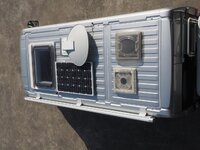
Our Murvi Morocco has a 100W solar panel which we have found adequate but since buying a compressor coolbox (Dometic CDF 25) we found after a couple of days off EHU in Brittany last September the batteries were getting a bit low. So it was time to look at fitting an extra panel. The problem is space on the roof is tight.

OI000037.jpg


You can see there is no room for a conventionally shaped panel, like the one already fitted. The only places are the strips of unused roof above and below the two roof lights you can see at the bottom of the picture. I did think about sticking a flexible panel across the front above the windscreen but felt it would be too vulnerable to branches.

I also looked at whether several smaller panels could be made to fit but there was no satisfactory solution I could find apart from fitting a long narrow panel across the roof of the 'van.

You can get slimline panels but they are not cheap. This is the one I went for (the 100W version):
http://www.csevolution.net/?q=node/74 This is just wide enough at 410 mm to fit between the current panel and the pair of roof lights, ie. across the middle of the roof. This still leaves space for a third panel across the rear, above the back doors, if needed later although this will be a slightly trickier fit as it will overhang the rear by a small amount. At 1.6m long it also goes across virtually the full width of the roof.

I bought the panel from these folk: http://www.motorcaravanning.co.uk/shopuk/solar_panels.htm who were very helpful with prompt delivery and their price, at a shade over £200 was half what someone else was selling the same panel for. Having now found out who makes the panel (which I didn't know until it arrived) I guess it may be possible to buy from the manufacturer directly even if you have to pick it up on a trip to Italy! Of course you can get 100W panels for under a £100 but not of this shape - and if you know of one please DON'T tell me! :)

I also needed to change the existing solar regulator from the very basic shunt regulator which was fitted. You can see it in the picture below, it has "beco" written on it and a green light. I had already removed it before realising I wanted a photograph so I refitted it for this shot, which is why it probably looks a bit untidy. The wires were originally all neatly clipped in.

P2060002.jpg


Curiously, or so it seemed to me, it has three wires coming from it, this is because one of the wires is a common negative for both the batteries and the solar panel. After a bit of head-scratching I decided I could use the same wires for the new controller which is a Victron 75/15, chosen because it gets good reviews, is very compact and the manufacturer was very helpful in responding to an email I sent them.

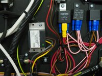
Here is the new controller in position.

P2060006.jpg


The brown loop of wire you can see connects the two negative terminals for the battery and solar feeds together. The single existing common negative is connected to one of these terminals. I'm not sure if this counts as a bodge - ideally I should have run a second wire but the common wire is very short - it only goes to the big busbar you can see on the right. I think I will leave it and check on a sunny day when there is a decent load running and see if it gets warm. :)

Note the load terminals of the controller are not used. This is fine and is what I confirmed with Victron by email. The actual MH 12 volt feeds all come off a fuse box which is fed by thick wires from the batteries. A separate meter senses the battery voltage and current.

The compact size of the Victron controller was a big bonus as space is limited and I still had to reposition one component, the curious black thing you can see arranged vertically with the thick red wires below the left hand edge of the controller. You can see it mounted horizontally in the second picture. It isn't a fuse, that's the red rectangular thing you can see on the left, perhaps it is an RF choke? Answers on a postcard please! (y)

Just need to wait for some daylight to see if it is all working. :)

The panel fit will happen when we get some dry weather. ;) So don't wait up expecting an update on this aspect of the job! The second panel is going to be wired in series with the first as recommended by Victron, this should be more efficient in low light levels.
 

Attachments

  • OI000037.jpg
    OI000037.jpg
    210.8 KB · Views: 126
  • P2060002.jpg
    P2060002.jpg
    224.3 KB · Views: 117
Last edited:
OP
OP
DBK

DBK

LIFE MEMBER
Jan 9, 2013
18,006
47,987
Plympton, Devon
Funster No
24,219
MH
PVC, Murvi Morocco
Exp
2013
There's a weak sun shining this morning through thin clouds so I checked to see if all was working. The panel was producing 19.5 volts, which is much higher than it ever did with the old controller. The charging current varied a bit between 0.2 and 0.6 amps with a battery voltage of around 13.5 volts. Not much of course but the sun is very low and the sunshine isn't even strong enough to cast a shadow - but at least it all seems to be working. Just need a couple of days of good weather forecast to fit the new panel. :)
 
OP
OP
DBK

DBK

LIFE MEMBER
Jan 9, 2013
18,006
47,987
Plympton, Devon
Funster No
24,219
MH
PVC, Murvi Morocco
Exp
2013
At the risk getting boring here is a graph which illustrates the relationship between panel voltage, current and power:

Solar_Panel_Power.JPG


Now this is for a 72 cell panel and a typical panel for a MH will only have 36, so the voltages in the graph above all have to be halved. Voc is the open circuit (no load) voltage and Vmp is the voltage for maximum power - V * I and all that.

Anyway, my panel is now running at a shade over 18 volts and should therefore be producing maximum power for the available light. Previously it was dragged down to the battery voltage and the power it produced would have been proportionally less.

Subscribers  do not see these advertisements


hilldweller

LIFE MEMBER
Dec 5, 2008
605
36,109
Macclesfield
Funster No
5,089
MH
Zilch Mk1
Exp
From Aug 2007
Just a word of caution, when I fitted my panel it was near to the TV aerial, bit like your dish and one day on it's first outing I saw very low current which I traced to one corner of the panel being shaded by the aerial. The drop was out of all proportion of of the area shaded so I guess kill just one cell and you kill the whole row of them. It would be interesting to hear if you find this.
 

Armytwowheels

LIFE MEMBER
Aug 10, 2012
6,466
14,801
Market Harborough
Funster No
22,346
MH
Carthago S Plus - Iveco
Exp
Since 2011
DBK, to my non-expert eye I would have thought the shade created by your sat dish was one of your biggest problems. We experimented the other week with Colin blocking off just one single square of the panel and me inside reading out the incoming amps, the difference was remarkable. Concluding that even if the panel was only partially covered it dramatically reduced the efficiency of the panel.

Maybe with your lack of space it might be worth considering one of those panels that go on the sat dish, you could then tilt it into the sun, which again makes a huge difference to how many amps you will get. I think some even follow the sun.
 
  • Like
Reactions: DBK
OP
OP
DBK

DBK

LIFE MEMBER
Jan 9, 2013
18,006
47,987
Plympton, Devon
Funster No
24,219
MH
PVC, Murvi Morocco
Exp
2013
Just a word of caution, when I fitted my panel it was near to the TV aerial, bit like your dish and one day on it's first outing I saw very low current which I traced to one corner of the panel being shaded by the aerial. The drop was out of all proportion of of the area shaded so I guess kill just one cell and you kill the whole row of them. It would be interesting to hear if you find this.

DBK, to my non-expert eye I would have thought the shade created by your sat dish was one of your biggest problems. We experimented the other week with Colin blocking off just one single square of the panel and me inside reading out the incoming amps, the difference was remarkable. Concluding that even if the panel was only partially covered it dramatically reduced the efficiency of the panel.

Maybe with your lack of space it might be worth considering one of those panels that go on the sat dish, you could then tilt it into the sun, which again makes a huge difference to how many amps you will get. I think some even follow the sun.

Yes to both, shading is a big problem and can indeed cut the power output out of all proportion to the amount of panel which is shaded. You can get panels which have diodes fitted to prevent or at least reduce this effect and perhaps I might replace the original panel with one like this next.

For the moment I can just swing the dish out of the way then lower it when amps are critical.

Subscribers  do not see these advertisements

 
OP
OP
DBK

DBK

LIFE MEMBER
Jan 9, 2013
18,006
47,987
Plympton, Devon
Funster No
24,219
MH
PVC, Murvi Morocco
Exp
2013
have you a pic of the new panel in place?
No, not fitted yet, waiting for better weather but basically it is going to be stuck in place. Assuming my measurements are accurate and it will actually fit! :LOL:
 

Minxy

LIFE MEMBER
Aug 22, 2007
32,623
66,460
E Yorks
Funster No
149
MH
Carthago Compactline
Exp
Since 1996, had Elddis/Swift/Rapido/Rimor/Chausson MHs. Autocruise/Globecar PVCs/Compactline i-138
Yes to both, shading is a big problem and can indeed cut the power output out of all proportion to the amount of panel which is shaded. You can get panels which have diodes fitted to prevent or at least reduce this effect and perhaps I might replace the original panel with one like this next.

For the moment I can just swing the dish out of the way then lower it when amps are critical.
The shading from your sat dish was my first thought of something which will reduce your input but looking at where the existing panel is fitted, there's plenty of room for it to be moved sideways nearer to your awning so that it doesn't get shaded at all ... might be worth doing that rather than replace it.

Subscribers  do not see these advertisements

 
  • Like
Reactions: DBK

Minxy

LIFE MEMBER
Aug 22, 2007
32,623
66,460
E Yorks
Funster No
149
MH
Carthago Compactline
Exp
Since 1996, had Elddis/Swift/Rapido/Rimor/Chausson MHs. Autocruise/Globecar PVCs/Compactline i-138
For the future you could look to get some smaller ones and link them together to get the right sizes for the gaps, eg:

Broken Link Removed
 
  • Like
Reactions: DBK

Wickolad

Free Member
Sep 10, 2013
490
542
Wickersley
Funster No
28,023
MH
Coachbuilt
Exp
Newbie to MH, 20yrs+ Caravanning.
Just something to Consider, but is your new 15A regulator up to coping with 2x 100W panels, my mppt regulator is 20A and states 200W.
 
  • Like
Reactions: DBK
OP
OP
DBK

DBK

LIFE MEMBER
Jan 9, 2013
18,006
47,987
Plympton, Devon
Funster No
24,219
MH
PVC, Murvi Morocco
Exp
2013
The shading from your sat dish was my first thought of something which will reduce your input but looking at where the existing panel is fitted, there's plenty of room for it to be moved sideways nearer to your awning so that it doesn't get shaded at all ... might be worth doing that rather than replace it.
Moving it is certainly worth looking at but I still need more power to match the extra drain from the new coolbox. A single 100W panel is not enough.

Subscribers  do not see these advertisements

 
OP
OP
DBK

DBK

LIFE MEMBER
Jan 9, 2013
18,006
47,987
Plympton, Devon
Funster No
24,219
MH
PVC, Murvi Morocco
Exp
2013
Just something to Consider, but is your new 15A regulator up to coping with 2x 100W panels, my mppt regulator is 20A and states 200W.
Yes, it is 75 volts and 15 amps. Putting the panels in series keeps the current the same as a single panel and doubles the voltage. I think it could even take a third panel wired the same way, but I'd ask the manufacturer first before trying that. :)
 

Wickolad

Free Member
Sep 10, 2013
490
542
Wickersley
Funster No
28,023
MH
Coachbuilt
Exp
Newbie to MH, 20yrs+ Caravanning.
Yes I agree, I hadn't figured on that. It's probably the better, more efficient way to do it taking volts drop / cable size into account. I may even get on my roof and reconfigure wiring of mine come spring time. I currently have 2x 100W panels in parallel. Thank you for that info, I hadn't considered that at all, Lance :)
Edit: just for further info, I notice in the pictures you have a Ctek MXS25 charger connected. Do you find this has any effect on the solar regulator when on EHU? I recently connected mine to give my batteries a good solid charge on recondition mode which can charge at up to 15.8 volts I believe at one stage for desulphation, it set an alarm off in the cab which I initially thought was coming from the Sargent MC50 interface unit until I discovered it was my Solar mppt controller, with F1 fault code. This only happened when I connected the Ctek, so at moment a bit bewildered. Having reset everything I've put Ctek on normal charge and all appears well.
 
Last edited:
  • Like
Reactions: DBK
OP
OP
DBK

DBK

LIFE MEMBER
Jan 9, 2013
18,006
47,987
Plympton, Devon
Funster No
24,219
MH
PVC, Murvi Morocco
Exp
2013
Yes I agree, I hadn't figured on that. It's probably the better, more efficient way to do it taking volts drop / cable size into account. I may even get on my roof and reconfigure wiring of mine come spring time. I currently have 2x 100W panels in parallel. Thank you for that info, I hadn't considered that at all, Lance :)
The instructions with the controller recommended series connection for greater efficiency and the folk I bought it off also said this works better in low light levels as well.

Subscribers  do not see these advertisements


Wickolad

Free Member
Sep 10, 2013
490
542
Wickersley
Funster No
28,023
MH
Coachbuilt
Exp
Newbie to MH, 20yrs+ Caravanning.
The instructions with the controller recommended series connection for greater efficiency and the folk I bought it off also said this works better in low light levels as well.
Thank you, well that's done it for me. We tend to do a fair few trips without EHU all year round. SWMBO insisted on use of hair dryer and straighteners or she wouldn't come. Hence the inverter takes its toll on batteries which is no problem in summer but plays hell in winter with low light/sun. It certainly makes sense, so seems the way to go. Thanks again, Lance
 
OP
OP
DBK

DBK

LIFE MEMBER
Jan 9, 2013
18,006
47,987
Plympton, Devon
Funster No
24,219
MH
PVC, Murvi Morocco
Exp
2013
Thank you, well that's done it for me. We tend to do a fair few trips without EHU all year round. SWMBO insisted on use of hair dryer and straighteners or she wouldn't come. Hence the inverter takes its toll on batteries which is no problem in summer but plays hell in winter with low light/sun. It certainly makes sense, so seems the way to go. Thanks again, Lance
I suspect the increase in efficiency isn't that great and in winter you are always going to struggle to recharge batteries drained by something like a hair drier - but every bit helps of course!
 
Sep 23, 2013
2,583
8,736
Lincs
Funster No
28,231
MH
Globecar Campscout
Exp
Since 2008 (started in a VW T4 campervan)
The instructions with the controller recommended series connection for greater efficiency and the folk I bought it off also said this works better in low light levels as well.
Agreed & that's how mine are wired.

BUT - it makes them particularly susceptible to shading. Shading on one panel of a pair in parallel badly affects the output of one panel but not the other. Shading on one panel wired in series badly affects the output of the whole array.

I did understand why when I researched it, but that's over a year ago & I've forgotten the explanation now.

Subscribers  do not see these advertisements

 
  • Like
Reactions: DBK

Don Quixote

Free Member
Jul 29, 2012
2,966
5,258
Lost in La Mancha, Spain
Funster No
22,171
MH
VW T6 Campervan
Exp
Not long enough, but a little common sense helps..........
Yes I agree, I hadn't figured on that. It's probably the better, more efficient way to do it taking volts drop / cable size into account. I may even get on my roof and reconfigure wiring of mine come spring time. I currently have 2x 100W panels in parallel. Thank you for that info, I hadn't considered that at all, Lance :)
Edit: just for further info, I notice in the pictures you have a Ctek MXS25 charger connected. Do you find this has any effect on the solar regulator when on EHU? I recently connected mine to give my batteries a good solid charge on recondition mode which can charge at up to 15.8 volts I believe at one stage for desulphation, it set an alarm off in the cab which I initially thought was coming from the Sargent MC50 interface unit until I discovered it was my Solar mppt controller, with F1 fault code. This only happened when I connected the Ctek, so at moment a bit bewildered. Having reset everything I've put Ctek on normal charge and all appears well.
I have the CTEK MX25 setup with my batteries and when on EHU use that and not the build in charger. The charge can go up to 15.8 as you say for desulphation, but this is only a very very short period and it pluses this is the "excite" the buildup of coating around the base of the plates. I have mine on normal 99% of the time, but will use the recondition mode once or twice a year. A great bit of kit as I have recovered a few batteries for folk that would have thrown the batteries away.
 
  • Like
Reactions: DBK
OP
OP
DBK

DBK

LIFE MEMBER
Jan 9, 2013
18,006
47,987
Plympton, Devon
Funster No
24,219
MH
PVC, Murvi Morocco
Exp
2013
Yes I agree, I hadn't figured on that. It's probably the better, more efficient way to do it taking volts drop / cable size into account. I may even get on my roof and reconfigure wiring of mine come spring time. I currently have 2x 100W panels in parallel. Thank you for that info, I hadn't considered that at all, Lance :)
Edit: just for further info, I notice in the pictures you have a Ctek MXS25 charger connected. Do you find this has any effect on the solar regulator when on EHU? I recently connected mine to give my batteries a good solid charge on recondition mode which can charge at up to 15.8 volts I believe at one stage for desulphation, it set an alarm off in the cab which I initially thought was coming from the Sargent MC50 interface unit until I discovered it was my Solar mppt controller, with F1 fault code. This only happened when I connected the Ctek, so at moment a bit bewildered. Having reset everything I've put Ctek on normal charge and all appears well.
Sorry, missed the second part about the Ctek charger - which had me digging out the manual for it!

According to this the recond program, where the voltage can go up to 15.8 is only for conventional lead acid or Ca/Ca batteries. It is not used for AGM or Gel batteries, which I have. It may go into the high frequency desulphation mode (which is different to recond) but the voltage for that peaks at 14.4 so I am hoping this won't be a problem. The recond mode it says is for batteries which have been deeply discharged or it can be run once a year. I can only suggest if you plan to run the recond program and it created faults it would be worthwhile disconnecting the solar controller.
 

Wickolad

Free Member
Sep 10, 2013
490
542
Wickersley
Funster No
28,023
MH
Coachbuilt
Exp
Newbie to MH, 20yrs+ Caravanning.
I have the CTEK MX25 setup with my batteries and when on EHU use that and not the build in charger. The charge can go up to 15.8 as you say for desulphation, but this is only a very very short period and it pluses this is the "excite" the buildup of coating around the base of the plates. I have mine on normal 99% of the time, but will use the recondition mode once or twice a year. A great bit of kit as I have recovered a few batteries for folk that would have thrown the batteries away.
Thank you for that, yes I agree it is an excellent bit of kit. I am actually planning to hardwire it in place of the charge unit on the Sargent psu225.
Which will hopefully keep my batteries in tip top condition. I think you're right about it just being put on normal charge mode 99% of the time, this appears to work fine on mine at moment, it was the recondition mode which my mppt solar charger didn't like, I'll have to do as DBK suggests and disconnect it when I do a recondition. Thanks again,

Lance :)

Subscribers  do not see these advertisements

 
  • Like
Reactions: DBK

Wickolad

Free Member
Sep 10, 2013
490
542
Wickersley
Funster No
28,023
MH
Coachbuilt
Exp
Newbie to MH, 20yrs+ Caravanning.
Sorry, missed the second part about the Ctek charger - which had me digging out the manual for it!

According to this the recond program, where the voltage can go up to 15.8 is only for conventional lead acid or Ca/Ca batteries. It is not used for AGM or Gel batteries, which I have. It may go into the high frequency desulphation mode (which is different to recond) but the voltage for that peaks at 14.4 so I am hoping this won't be a problem. The recond mode it says is for batteries which have been deeply discharged or it can be run once a year. I can only suggest if you plan to run the recond program and it created faults it would be worthwhile disconnecting the solar controller.
Hi DBK, thank you for the useful information and taking the time and trouble to pass this on to me. Much appreciated.

Lance :)
 
  • Like
Reactions: DBK

hilldweller

LIFE MEMBER
Dec 5, 2008
605
36,109
Macclesfield
Funster No
5,089
MH
Zilch Mk1
Exp
From Aug 2007
said this works better in low light levels as well.

It has to be. If a panel is making 12V then no charge but two in series would be 24V so something may get through.

For a month our 100W has run water pump, lights and a couple of hours TV a night. I see about 2A charge. Overcast right now and only 0.9A.

Hook up runs fridge and some electric heating, it's pretty cold at night.
 
  • Like
Reactions: DBK
OP
OP
DBK

DBK

LIFE MEMBER
Jan 9, 2013
18,006
47,987
Plympton, Devon
Funster No
24,219
MH
PVC, Murvi Morocco
Exp
2013
It has to be. If a panel is making 12V then no charge but two in series would be 24V so something may get through.

For a month our 100W has run water pump, lights and a couple of hours TV a night. I see about 2A charge. Overcast right now and only 0.9A.

Hook up runs fridge and some electric heating, it's pretty cold at night.
That sounds about what I'm getting now with the single 100W panel. When the sun was out this morning it could produce about 2 amps with a battery voltage of 13 volts, so about 25W from the panel. Given how low the sun is at this time of year I was quite pleased. I measured the current by turning on led lights, which I know take about 0.4 amps, until the meter showed neither charge or discharge, this was with five lights turned on. The sun was also on the satellite dish side so would have been casting a shadow.

Subscribers  do not see these advertisements


meanderer

Free Member
Jan 28, 2016
13
4
Devon
Funster No
41,494
MH
Low Profile
Exp
Since 2009
BUT - it makes them particularly susceptible to shading. Shading on one panel of a pair in parallel badly affects the output of one panel but not the other. Shading on one panel wired in series badly affects the output of the whole array.

This is very true and I found this out when working on mini panels for marine systems. Two panels subjected to the same light source are better in series. Where one is partially shaded, it's impedence (effective resistance) rises and that then hits the ability of the other series panel to provide power.
For our work system I now use two separate MPPT controllers to maximise the power from each panel - it also means the panels can be mounted with different orientation to each other.

When you need maximum power - try to park with the offside of the van to the North... No shading issues then!

Good Luck!
 
  • Like
Reactions: DBK
OP
OP
DBK

DBK

LIFE MEMBER
Jan 9, 2013
18,006
47,987
Plympton, Devon
Funster No
24,219
MH
PVC, Murvi Morocco
Exp
2013
I'm still waiting for it to warm up before I fit the new panel but at least this enforced delay has meant I have been able to see how the new controller is getting on and so far I am very impressed. Of course this is a very subjective test but on the day the picture below was taken the ammeter was showing a charge of around 1.5A which peaked every so often at 2A. Which I think isn't bad for a 100W panel at this time of the year. You can see how low the sun is, which is behind a cloud, in the picture below.

DSC_0033.JPG


What is particularly interesting is the satellite dish is shading the panel but the output is still quite good in the circumstances. This I think is because the panel I have has the bypass diodes which reduce the detrimental effects of shading.
 
OP
OP
DBK

DBK

LIFE MEMBER
Jan 9, 2013
18,006
47,987
Plympton, Devon
Funster No
24,219
MH
PVC, Murvi Morocco
Exp
2013
The sun came out today so it was out with the high step ladder and see if all the bits fit together.

OI000043.jpg


Fortunately, they did. :)

The panel nearest the camera is the existing one and the new one is the long thin one running across the roof of the van beyond it.

The picture just shows the panel resting on the supports, no holes drilled at this point.

Having decided it all does fit, and it only just does, I drank a couple of cups of tea and decided on how to secure everything. I think there are several approaches but given I was working on my own I decided to fit the supports to the roof first then fit the panel. This should work but needed accuracy!

Using 3mm tile spacers I drilled a 2mm pilot hole in the panel frame and 5mm clearance holes in the supports.

OI000049.jpg


In the picture above I've fitted 8 * 1" SS self-tappers (1.25" might be better in retrospect) into the side frame of the panel. The stand off distance (gap :)) you can see is due to the tile spacers.

What you should also see in the picture is the angles are all "wrong" because the roof of the van isn't flat, it is curved which adds an extra fun element. I decided to fit the supports flat on the roof and accommodate the slope in the fit between support and the panel.

The masking tape is there to mark where the support will fit as a guide when putting the Sikaflex on later.

Having marked around all the support I could reach with the masking tape and drilled pilot holes into the roof I took everything off and using one of the supports to show the outline of footprint I put masking tape on the roof around the base of each foot on the bits I couldn't reach with the panel fitted.

Before fitting the panel I connected the electric cable to it and then ran a layer of Sikaflex around the inside of the masked off area. Having first roughened the paintwork and used the Sikaflex 205 activator.

The roof of course is not only curved it has grooves in it. These I filled with a bit of 6mm Foamex which is the white plastic board frequently used by sign writers. Tile spacers were also used between the roof and the supports.

Once the supports were fitted and screwed down with 8 * 3/4" SS screws I could fit the panel and after running a bead of Sikaflex around the joint I refitted the screws and tightened them up, using tile spacers again to ensure the mastic wasn't squeezed out of the joint.

As a small frost is forecast for tonight I covered everything over with cardboard and dog towels and wound the heating up in the van up to 25C.

By the time this was all done it was dark! Tomorrow I will connect the electrics after a visit to the Fang Farrier for a dental check up! Which was scheduled, solar panels don't cause tooth decay. :D

Subscribers  do not see these advertisements

 
Last edited:
Sep 3, 2012
7,528
25,994
Cheshire
Funster No
22,759
MH
C Class Elddis 175
Exp
8+ years
A good fitting panel(y) and from your original roof view I suppose you could add another at the rear of the roof albeit an awkward slope
 
  • Like
Reactions: DBK
OP
OP
DBK

DBK

LIFE MEMBER
Jan 9, 2013
18,006
47,987
Plympton, Devon
Funster No
24,219
MH
PVC, Murvi Morocco
Exp
2013
A good fitting panel(y) and from your original roof view I suppose you could add another at the rear of the roof albeit an awkward slope
Yes, there is room across the back, in fact that was where I was originally going to fit this one. It would slightly overhang by a centimetre or so but if I used something like aluminium channels it could be mounted more or less flat.

I'll see how I get on with 200W and perhaps fit a third if needed. I don't have a big inverter but if we did then it would be a no brainer.
 
OP
OP
DBK

DBK

LIFE MEMBER
Jan 9, 2013
18,006
47,987
Plympton, Devon
Funster No
24,219
MH
PVC, Murvi Morocco
Exp
2013
I finished off the wiring this afternoon, mounting a waterproof junction box on the roof.

OI000047.jpg


It might look a bit odd, sitting at an angle but the problem was there wasn't a lot of cable between the existing panel and the point where the feed goes down through the roof. So after I had cut this in half and tried everything for size there was really only one position the junction box could go.

The picture above shows it completed. It is sitting on a couple of blobs of Sikaflex and secured by two screws. The terminal block is also stuck down with Sikaflex. I also drilled a drain hole in the bottom, which you can just see on the right.

I was slightly disappointed to see the existing cable just looked like 13A flex to me and is a bit thin. Fortunately it isn't very long as it stops where it enters the vehicle as there is a plug and socket at that point and the cable inside the van is thicker. The brown wire is positive, blue negative and the two panels have been wired in series.

The sun was behind some trees by the time I finished but I still measured 36 volts across both panels so it is all working.

We shall see how it performs tomorrow - if we get some sun! :)

Subscribers  do not see these advertisements


Join us or log in to post a reply.

To join in you must be a member of MotorhomeFun

Join MotorhomeFun

Join us, it quick and easy!

Log in

Already a member? Log in here.

Latest journal entries

Funsters who are viewing this thread

Back
Top